6. EM GUI orientation
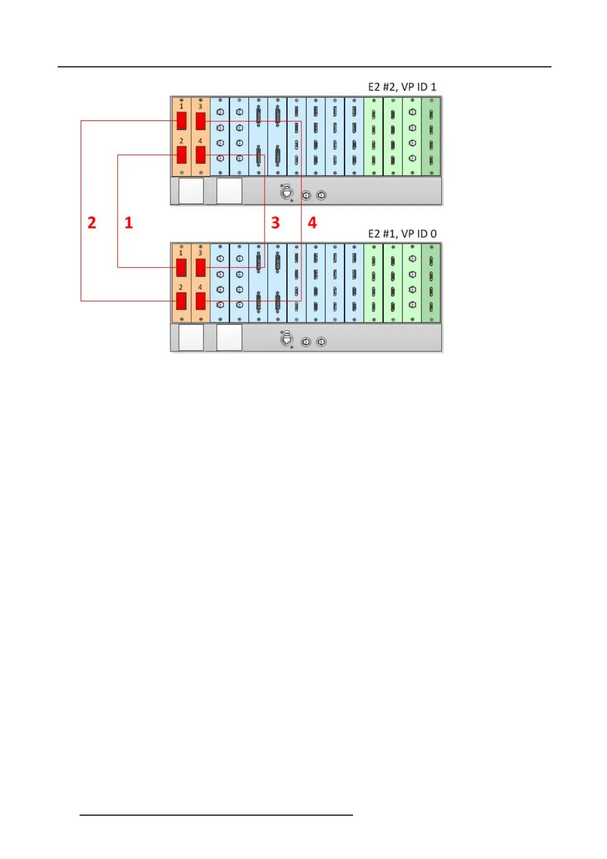
Image 6-29
Cabling between two E2 units
Event Master Configuration for Two E2s
1. Start the Event M aster Toolset version 1.5 or higher.
2. Make su re that the two E2s are discovered on the network and that they have different Unit IDs.
3. Drop one the two E2s in the G UI.
4. Then drop the second E 2.
You will be presented the option to add as a new system, add as a master, or add as a slave.
5. Select either add as a master or add as a slave.
6. (Optional) At this point it is suggested that you s elect and name appropriately each E 2 so that yo u can identify it in your setup.
HowtoLinkanE2UnitandanS3–4KUnit
Each E2 comes equipped with two Link cards, alway s located in s lots 1 and 2. Each S3–4K has a single Link card in slot 1. Link
cards are identified by a yellow stripe at the top. M ake sure to use the locking mec hanism and then push each cable until it locks
in plac e.
Connect the Link cables provided with each unit between the Link connectors as follows:
• E2 VP ID 0, Link C ard slot 1, Link 1 >> S 3–4K V P ID 1 , Link Card slot 1, Link 2
• E2 VP ID 0, Link C ard slot 1, Link 2 >> S 3–4K V P ID 1 , Link Card slot 1, Link 1
See image 6-30 for an example of the cabling be tween a n E2 unit and an S 3–4K unit.
140
R5905948 EVENT MASTER DEVICES 17/07/2017