6. EM GUI orientation
Image 6-36
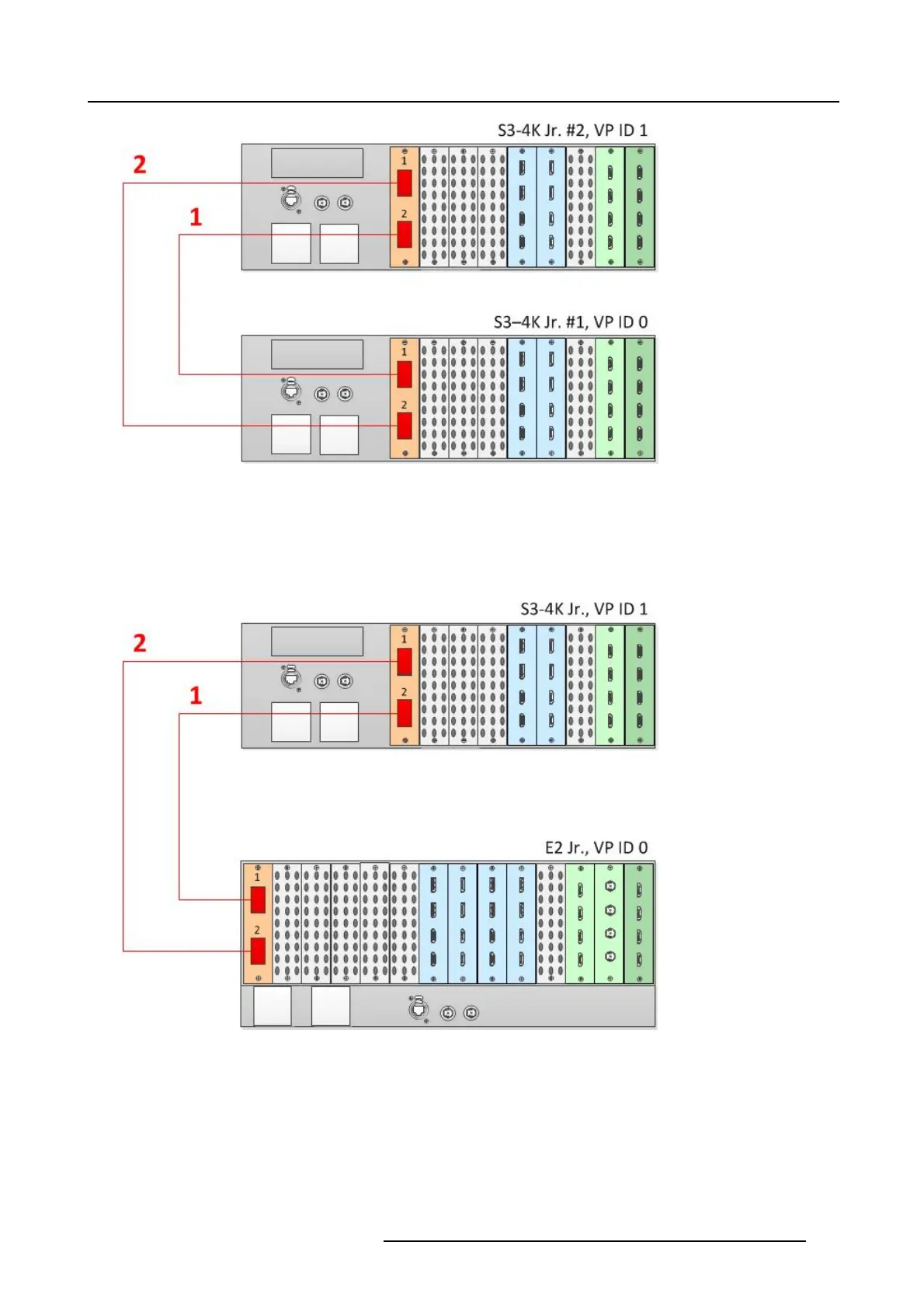
Cabling between two S3–4K Jr. units
To link an E2 Jr. unit to a n S3–4K Jr. unit, connect Link cables between the Link con nectors as follows:
• VP ID 0, L ink Ca rd slot 1, L ink 1 >> VP ID 1, Link Card slot 1, Link
2
• VP ID 0, L ink Ca rd slot 1, L ink 2 >> VP ID 1, Link Card slot 1, Link 1
See image 6-37 for an example of the ca bling between an E2 Jr. unit and an S 3–4K unit.
Image 6-37
Cabling between an E2 Jr. unit and an S3–4K Jr. unit
Event Master Configuration
1. Start the Event M aster Toolset version 4.1 or higher.
2. Make s ure that both units are discovered on the network and that they have different U nit IDs.
3. Drop the first in the GUI.
4. Drop the second u nit in the GUI.
You will be presented the option to add as a new system, add as a master, or add as a slave. An S3–4K can be added as a
Master or Slave to an E2.
R5905948 EVENT MASTER DEVICES 17/07/2017
147