9. General operation example
Image 9-9
C6: Add Aux Destinations
1. From the diagram area click on the DS M o utput. T he connector will be highlighted.
2. Click on the +Add Aux De s tinatio n blue button to assign the DSM output to an A ux destination.
3. When the Aux destination is created a box appears next to the E2 diagr am.
4. Double click on the Destination1 area in the Nam e list to edit the name.
5. When the area turns blue, click the eraser icon to clear the field.
6. Type a new name, “DS M”. Hit enter when done.
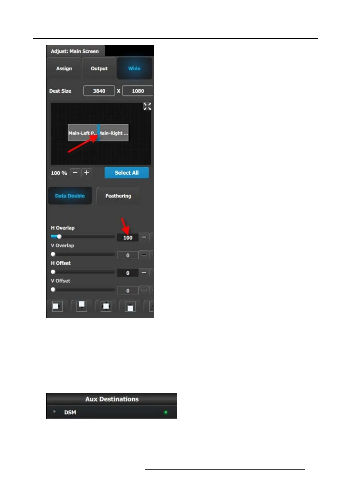
Image 9-10
C7: Add MVR Output
1. Click on the MV R tab to select the MVR outputs that will be defined.
2. Click on the +Add MVR Output blue button to enter the Add m ode.
R5905948 EVENT MASTER DEVICES 17/07/2017
269