3. General
b) Measure the distance between the front and r ear rack rails. Remove the mounting screws that secure e ach side rail to the
chassis, and then adjust the spacing of each side rail as necess ary. The S3 uses four mounting screws on each side rail; the
EX uses two mounting screws on each side rail.
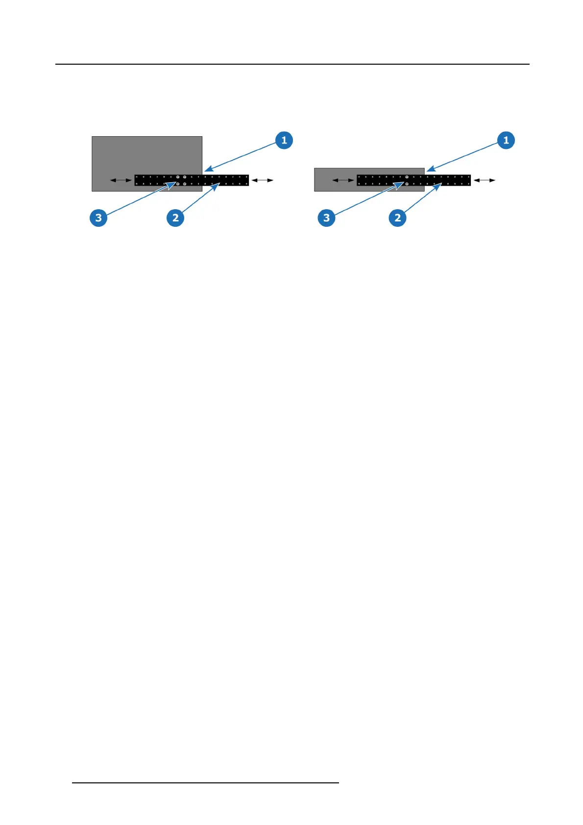
Image 3-15
S3–4K series side rail and mounting screws
1 Chassis rear
2Siderail
3 Mounting screws
Image 3-16
EX expansion box side rail and mounting screws
1 Chassis rear
2Siderail
3 Mounting screws
c) Re-install the moun ting screws. W hen properly adjusted, the end of each side rail will protrude through the slot in the rear
mounting bracket, once the chassis is rack mounted.
2. Lift the chassis, and while supporting it, slide the side rails through the slots in the rear mounting brackets.
3. While continuing to s upport the chassis, install and tighten the two lower screws.
4. Finally, install and tighten the two upp ers screws in the rack rail.
40
R5905948 EVENT MASTER DEVICES 17/07/2017