DGS-3630 Series Layer 3 Stackable Managed Switch Web UI Reference Guide
391
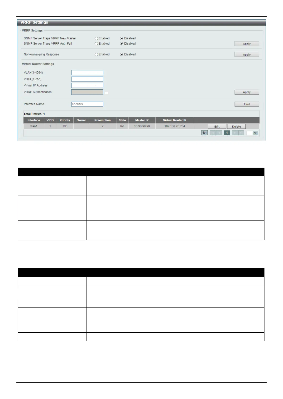
Figure 6-241 VRRP Settings Window
The fields that can be configured in VRRP Settings are described below:
Parameter Description
SNMP Server Traps VRRP
New master
Select to enable or disable the SNMP server traps feature for the new VRRP
master. If enabled, once the device has transitioned to the master state, a trap will
be sent out.
SNMP Server Traps VRRP
Auth Fail
Select to enable or disable the SNMP server traps feature for authentication
failures. If enabled, if a packet has been received from a router whose
authentication key or authentication type conflicts with this router's authentication
key or authentication type, then a trap will be sent out.
Non-owner-ping Response
Select to enable or disable the non-owner ping response feature here. This
feature is used to enable the virtual router in the master state to respond to ICMP
echo requests for an IP address not owned but associated with this virtual router.
Click the Apply button to accept the changes made.
The fields that can be configured in Virtual Router Settings are described below:
Parameter Description
VLAN
Enter the VLAN interface ID used here. The range is from 1 to 4094.
VRID
Enter the virtual router ID used here. This ID is used to identify the virtual router in
the VRRP group. The range is from 1 to 255.
Virtual IP Address
Enter the IPv4 address for the created virtual router group here.
VRRP Authentication
Select to enable and then enter the plain text authentication password for VRRP
authentication on the interface here. This string can be up to 8 characters long.
The authentication is applied to all virtual routers on this interface. The devices in
the same VRRP group must have the same authentication password.
Interface Name
Enter the interface name used here. This name can be up to 12 characters long.
Click the Apply button to accept the changes made.
Click the Find button to locate a specific entry based on the information entered.
Click the Edit button to modify the specified entry.
Click the Delete button to delete the specified entry.
 Loading...