DGS-3630 Series Layer 3 Stackable Managed Switch Web UI Reference Guide
586
Parameter Description
• Both - Specifies to count ingress and egress traffic.
Click the Apply button to accept the changes made.
Click the Delete button to delete the specified entry based on the information entered/selected.
The fields that can be configured for VLAN Counter Table are described below:
Parameter Description
Interface VLAN
Enter the VLAN ID that will be used in the display here. The range is from 1 to
4094. Select the All option to display counter information associated with all
VLAN interfaces.
Traffic Direction
Select the traffic direction to display here. Options to choose from are:
• RX - Specifies to display ingress traffic count settings.
• TX - Specifies to display egress traffic count settings.
• Both - Specifies to display ingress and egress traffic count settings.
Click the Find button to display entries in the table based on the information entered/selected.
Enter a page number and click the Go button to navigate to a specific page when multiple pages exist.
Utilization
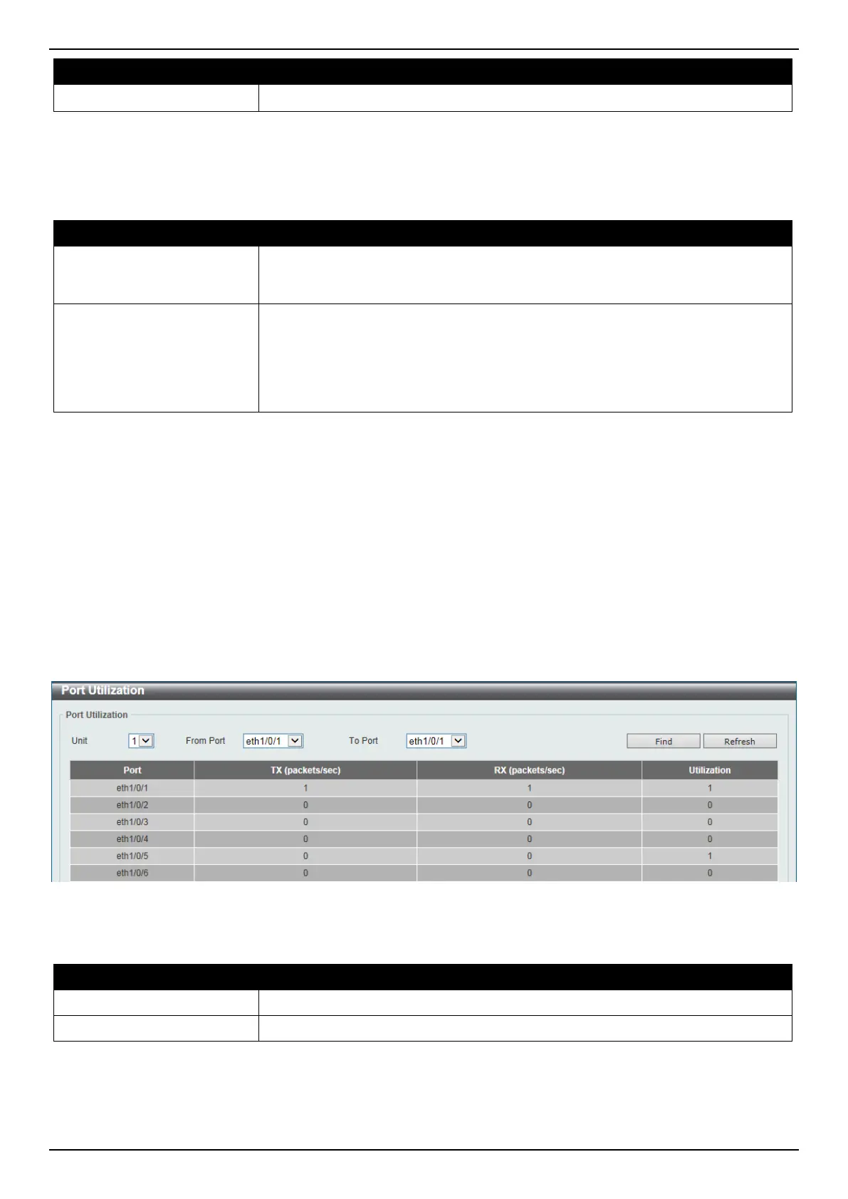
Port Utilization
This window is used to view the port utilization table.
To view the following window, click Monitoring > Utilization > Port Utilization, as shown below:
Figure 13-2 Port Utilization Window
The fields that can be configured are described below:
Parameter Description
Unit
Select the Switch unit that will be used here.
From Port - To Port
Select the range of ports that will be used here.
Click the Find button to display entries in the table based on the information entered/selected.
Click the Refresh button to refresh the information displayed in the table.
 Loading...