DGS-3630 Series Layer 3 Stackable Managed Switch Web UI Reference Guide
624
Parameter Description
Click the Start button to initiate the route trace for each individual section.
The fields that can be configured in IPv6 Trace Route are described below:
Parameter Description
IPv6 Address
Select and enter the IPv6 address of the destination here.
Domain Name
Select and enter the domain name of the destination here.
Initial TTL
Enter the initial Time-To-Live (TTL) value here. The range is from 1 to 255.
Max TTL
Enter the Time-To-Live (TTL) value of the trace route request here. This is the
maximum number of routers that a trace route packet can pass. The trace route
option will cross while seeking the network path between two devices. The range
for the TTL is 1 to 255 hops.
Port
Enter the port number here. The value range is from 1 to 65535.
Timeout
Enter the timeout period while waiting for a response from the remote device
here. A value of 1 to 65535 seconds can be specified. The default is 5 seconds.
Length
Enter the length value here. This specifies the number of bytes of the outgoing
datagram. The range is from 1 to 1420 bytes.
Frequency
Enter the frequency time for the trace route here. The range is from 0 to 86400.
Source IPv6 Address
Enter the source IPv6 address here. The specified IPv6 address must one of the
IPv6 addresses configured for the Switch.
Probe Number
Enter the probe time number here. The range is from 1 to 1000. If unspecified, the
default value is 1.
Click the Start button to initiate the route trace for each individual section.
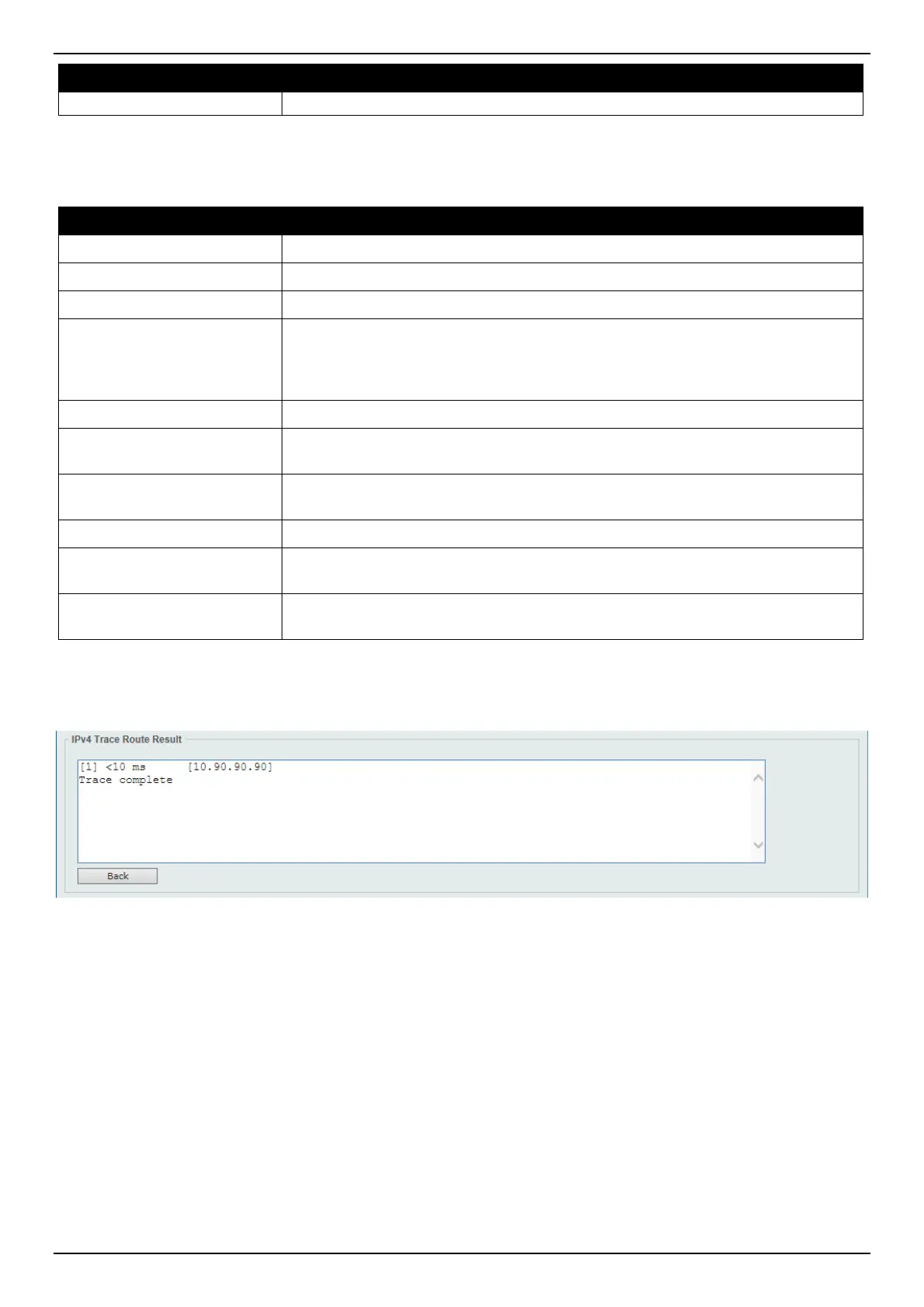
After clicking the Start button in IPv4 Trace Route section, the following IPv4 Trace Route Result section will appear:
Figure 15-25 Trace Route (Start) Window
Click the Back button to stop the trace route and return to the IPv4 Trace Route section.
Reset
This window is used to reset the Switch’s configuration to the factory default settings.
To view the following window, click Tools > Reset, as shown below:
 Loading...