DGS-3630 Series Layer 3 Stackable Managed Switch Web UI Reference Guide
574
The fields that can be configured are described below:
Parameter Description
IPv4 Address
Select and enter the FEC IPv4 address here whose LSP connectivity will be
checked.
Mask
Select and enter the FEC subnet mask here.
VC
Select and enter the FEC VC IP address here.
VC ID
Select and enter the FEC VC ID here.
Ping Times
Enter the ping time amount here. This is the amount of ping packets that will be
sent out. The range is from 1 and 255.
Timeout
Enter the ping timeout value here. The range is from 1 to 99 seconds.
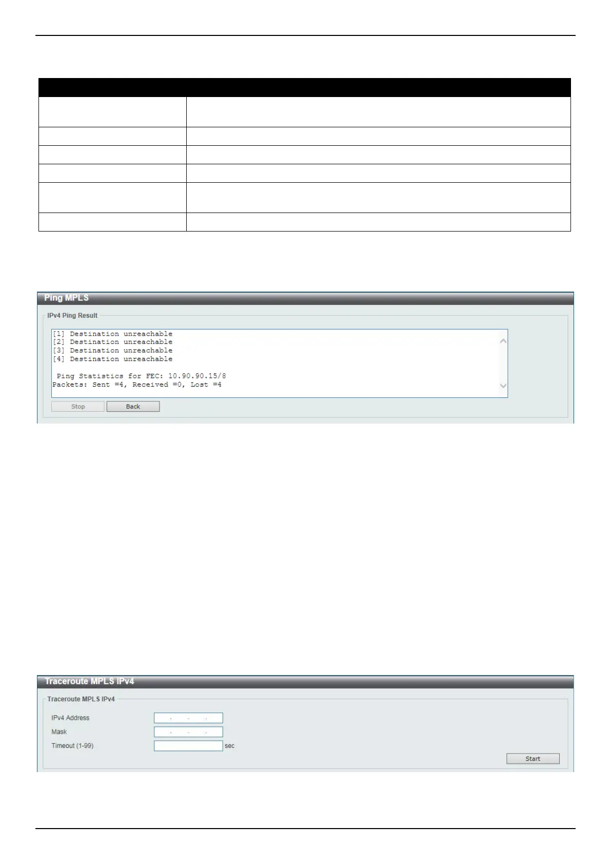
Click the Start button to initiate the MPLS ping.
After clicking the Start button, the following page will appear.
Figure 11-24 Ping MPLS (Start) Window
Click the Stop button to stop the MPLS ping.
Click the Back button to return to the previous window.
Traceroute MPLS IPv4
This window is used for hop-by-hop fault localization as well as path tracing the LSP of the specified FEC. If there is
no LSP for the specified FEC, the “Destination unreachable” message will be displayed. Otherwise, MPLS echo
request messages will be sent out to along the LSP of the specified FEC. The TTL in the outmost label of the MPLS
echo requests is set successively to 1, 2, 3, and so on. It forces the echo request expired at each successive LSR
along the LSP. The LSR returns an MPLS echo reply. If the sender cannot receive a reply before the timeout, the
trace route will stop.
To view the following window, click MPLS > Traceroute MPLS IPv4, as shown below:
Figure 11-25 Traceroute MPLS IPv4 Window
 Loading...