DGS-3630 Series Layer 3 Stackable Managed Switch Web UI Reference Guide
293
Click the Find button to locate a specific entry based on the information entered.
Click the Show All button to display all the entries.
Click the Edit button to modify the specified entry.
Enter a page number and click the Go button to navigate to a specific page when multiple pages exist.
After clicking the Edit button, the following page will appear.
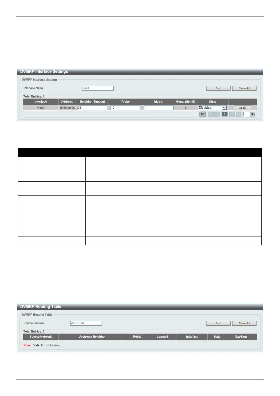
Figure 6-113 DVMRP Interface Settings (Edit) Window
The fields that can be configured in the table are described below:
Parameter Description
Neighbor Timeout
Enter the neighbor lifetime value here. If the router has not received a probe
message from a neighbor after the neighbor timeout interval, the neighbor is
considered to be down. The range is from 1 to 65535 seconds. By default, this
value is 35 seconds.
Probe
Enter the DVMRP probe interval value here. The range is from 1 to 65535
seconds. By default, this value is 10 seconds.
Metric
Enter the metric value here. The range is from 1 to 32. A value of 32 means it is
unreachable. For each source network reported, a route metric is associated with
the route being reported. The metric is the sum of the interface metrics between
the router originating the report and the source network. For DVMRP, the metric
with 32 means it is unreachable. This limits the breadth across the whole DVMRP
network and is necessary to place an upper limit on the convergence time of the
protocol.
State
Select to enable or disable the DVMRP feature on the selected interface.
Click the Apply button to accept the changes made.
DVMRP Routing Table
This window is used to find and display DVMRP routing information.
To view the following window, click L3 Features > IP Multicast Routing Protocol > DVMRP > DVMRP Routing
Table, as shown below:
Figure 6-114 DVMRP Routing Table Window
The fields that can be configured are described below:
 Loading...