DGS-3630 Series Layer 3 Stackable Managed Switch Web UI Reference Guide
515
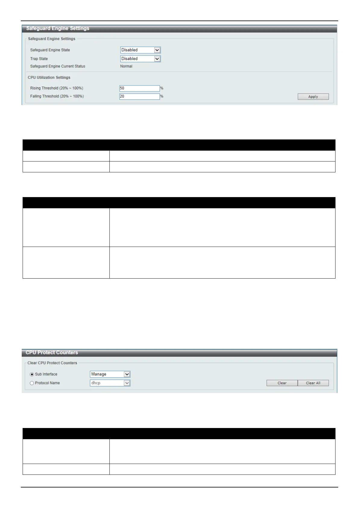
Figure 9-78 Safeguard Engine Settings Window
The fields that can be configured in Safeguard Engine Settings are described below:
Parameter Description
Safeguard Engine State
Select to enable or disable the safeguard engine feature here.
Trap State
Select to enable or disable the safeguard engine trap state here.
The fields that can be configured in CPU Utilization Settings are described below:
Parameter Description
Rising Threshold
Enter the rising threshold value here. This value must be between 20% and
100%. This value is used to configure the acceptable level of CPU utilization
before the Safeguard Engine mechanism is enabled. Once the CPU utilization
reaches this percentage level, the Switch will move into Exhausted mode, based
on the parameters provided in this window.
Falling Threshold
Enter the falling threshold value here. This value must be between 20% and
100%. This value is used to configure the acceptable level of CPU utilization as a
percentage, where the Switch leaves the Safeguard Engine state and returns to
normal mode.
Click the Apply button to accept the changes made.
CPU Protect Counters
This window is used to view and clear the CPU protection counter information.
To view the following window, click Security > Safeguard Engine > CPU Protect Counters, as shown below:
Figure 9-79 CPU Protect Counters Window
The fields that can be configured are described below:
Parameter Description
Sub Interface
Select the sub-interface option here. Options to choose from are Manage,
Protocol, Route, and All. This option specifies to clear the CPU protect related
counters of sub-interfaces.
Protocol Name
Select the protocol name option here.
 Loading...