A
B
C
D
E
F
G
H
L
M
N
P
Uso e manutenzione
Maintenance operations
sezione / section
D 5
48 ST3 - M.Y. 2004 - edizione/edition 00
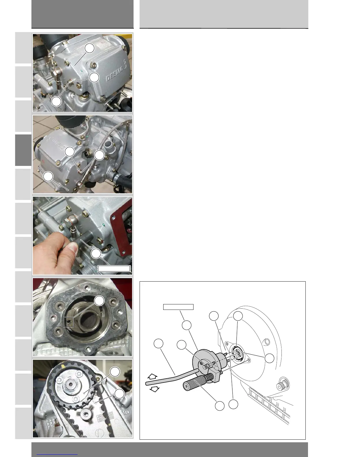
Fit the locking tool (14) to the crank-
shaft so that the teeth (E) engage in
the holes (F) in the crank end.
Screw the screw (G) on the tool (16)
into the crank end and tighten it.
Use handle (H) to turn the tool gradu-
ally until the locking screw (L) engag-
es with the hole in the alternator
casing.
Tighten the locking screw (L) firmly by
hand.
Remove the screws (16) and spring
washers (17) from the cylinder head
casings (15).
Lock the camshafts of both heads by
fitting the locking tools (18) into the
head casings (15).
Manually turn the pulleys as shown in
the figure until the end of the tool en-
gages with the hole (M) in the cam.
Correct alignment is easily achieved
by aligning the hole (N) with the arrow
(P) on the inner cam drive casing.
Installare l’attrezzo di bloccaggio (14)
sull’albero motore inserendo i dentini
(E) nelle cave (F) dell’albero stesso.
Imputare la vite (G) dell’attrezzo (16)
sull’albero motore e serrarla.
Aiutandosi con la maniglia (H)
compiere piccoli movimenti rotatori
per imputare correttamente il
tampone (L) sul coperchio
alternatore.
Serrare a fondo (manualmente)
il tampone (L).
Rimuovere dal cappellotto laterale
(15) la vite (16) recuperando la
rosetta (17).
Bloccare l’albero distribuzione di
entrambe le teste avvitando nel
cappellotto laterale (15) l’attrezzo (18).
Girare a mano le pulegge come
mostra la figura fino a quando
l’estremità dell’atrezzo si inserisce
nella cava (M) dell’albero
distribuzione.
La posizione di allineamento è
facilmente ottenibile allineando il foro
(N) e la freccia (P) presente sulla
cartella interna di distribuzione.
88713.2011
FE
F
E
G
H
L
14
15
16
17
16
17
15
88713.2257
18
M
N
P