6 Input/Output
6.7 Output
Remote Command
:OUTPut:DBUS2[:STATe] OFF | ON | 0 | 1
:OUTPut:DBUS2[:STATe]?
Example
:OUTP:DBUS2 ON
Notes If this command is sent while running a measurement that does not support Wideband Digital Bus,
the message “Settings conflict; Feature not supported for this measurement” is displayed
Dependencies Requires option RTS or control is not displayed
Digital Bus Out and Wideband Digital Bus cannot both be ON at the same time, so:
–
When Wideband Digital Bus is turned ON, if Digital Bus Out is already ON, an advisory message is
displayed, “Wideband Digital Bus On, Digital Bus (narrow band) forced to Off”
–
When Digital Bus Out is turned ON, if Wideband Digital Bus is already ON, an advisory message is
displayed, “Digital Bus (narrow band) On, Wideband Digital Bus forced to Off”
Preset
OFF
Set by Restore Input/Output Defaults
State Saved Saved in Input/Output State
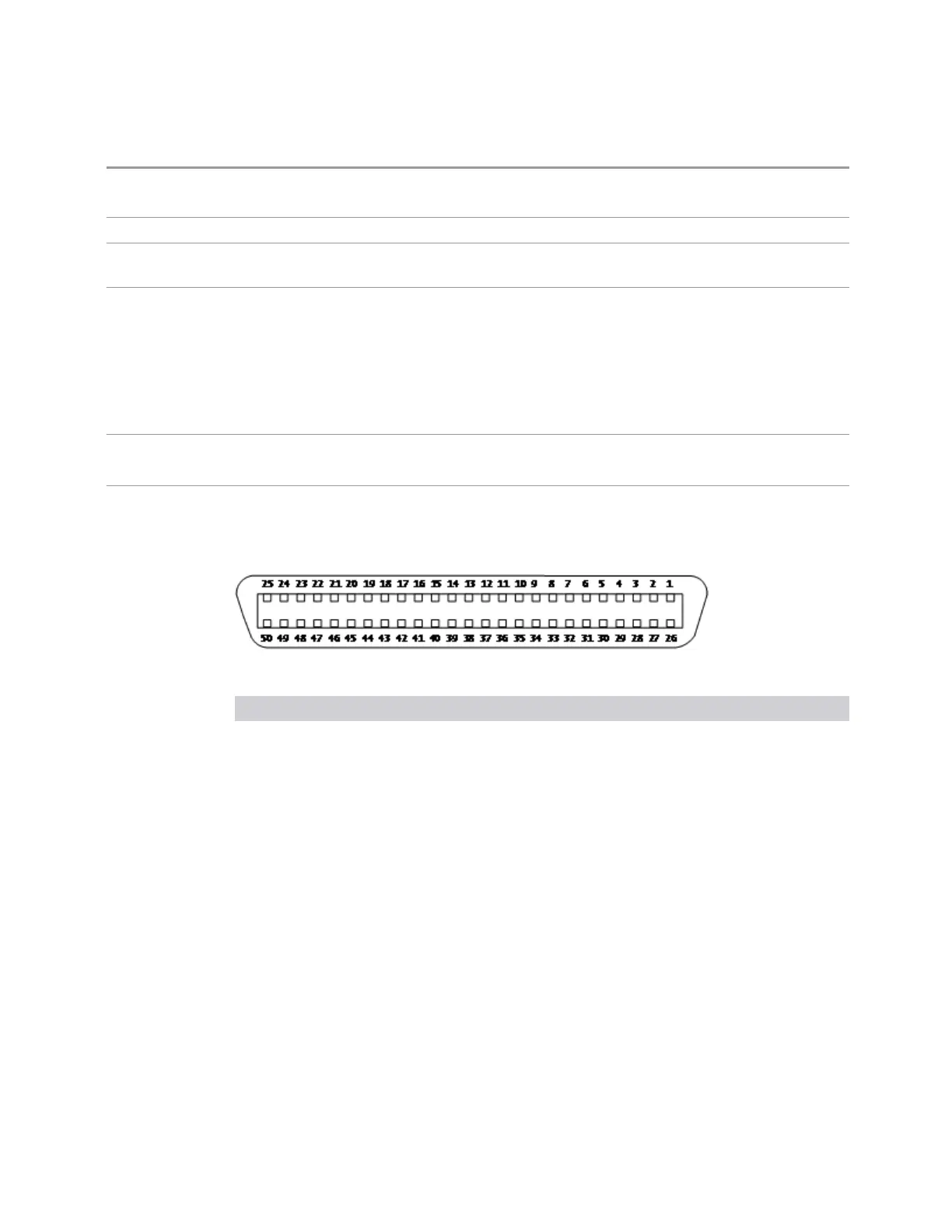
Here is the Wideband LVDS connector as viewed from the rear panel. The pin
assignments are listed below:
I-Cable
Connection “-“ pin # “+” pin #
GND 1 26
N/C 2 27
Stream_I[00] 3 28
Stream_I[01] 4 29
Stream_I[02] 5 30
Stream_I[03] 6 31
GND 7 32
Stream_I[04] 8 33
Stream_I[05] 9 34
Stream_I[06] 10 35
Stream_I[07] 11 36
GND 12 37
Stream_I[08] 13 38
Stream_I[09] 14 39
Vector Modulation Analyzer Mode User's &Programmer's Reference 2254

 Loading...


