9 Programming the Instrument
9.4 Status Register System & STATus Subsystem
–
Set :INITiate:CONTinuous OFF
–
Set/enable the status registers
–
Restart the measurement (send :INIT)
9.4.5 Status Register Bit Parameters
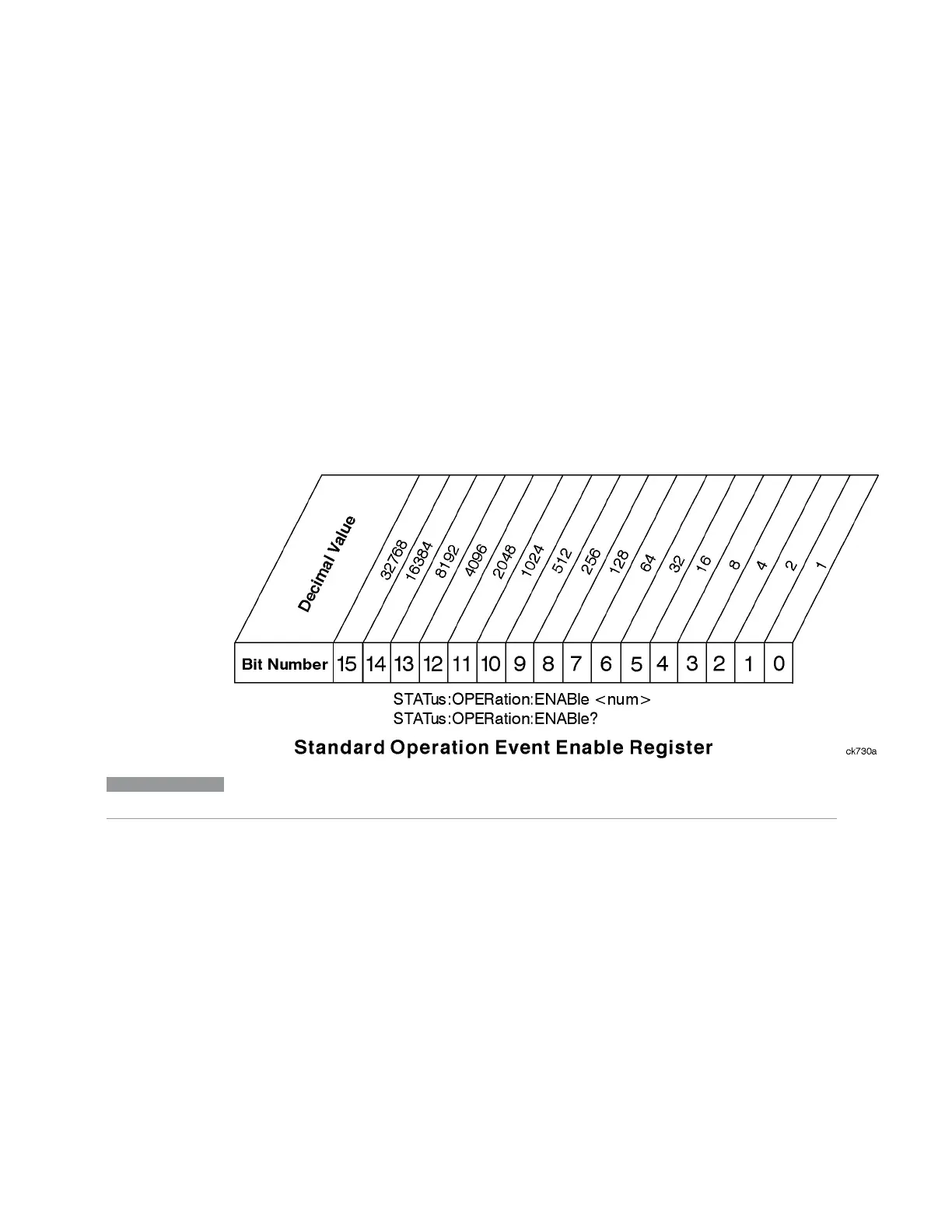
The diagram below shows a typical status register, in this case the "Operation
Enable" on page 2587 Register. Each bit in a register is represented by a numerical
value based on its location. When a command requires a bit pattern to be sent as its
parameter, that can be entered as a numeric value using decimal or hexadecimal
representations. (where 0 to 32767 is equivalent to #H0 to #H7FFF). If you want to
enable more than one bit, you send the sum of all the bits that you want to monitor.
NOTE
Bit 15 is not used to report status.
Example 1
To enable bit 0 and bit 6 of standard event status register, you would send the
command *ESE 65 because 1 + 64 = 65
The results of a query are evaluated in a similar way. If the *STB? command returns
a decimal value of 140, (140 = 128 + 8 + 4) then bit 7 is true, bit 3 is true and bit 2 is
true
Example 2
Suppose you want to know if an Auto-trigger Timeout occurs, but you only cared
about that specific condition. So you would want to know what was happening with
bit 10 in the Status Questionable Integrity register, and not about any other bits
Vector Modulation Analyzer Mode User's &Programmer's Reference 2578

 Loading...


