RM0008 Controller area network (bxCAN)
Doc ID 13902 Rev 12 659/1096
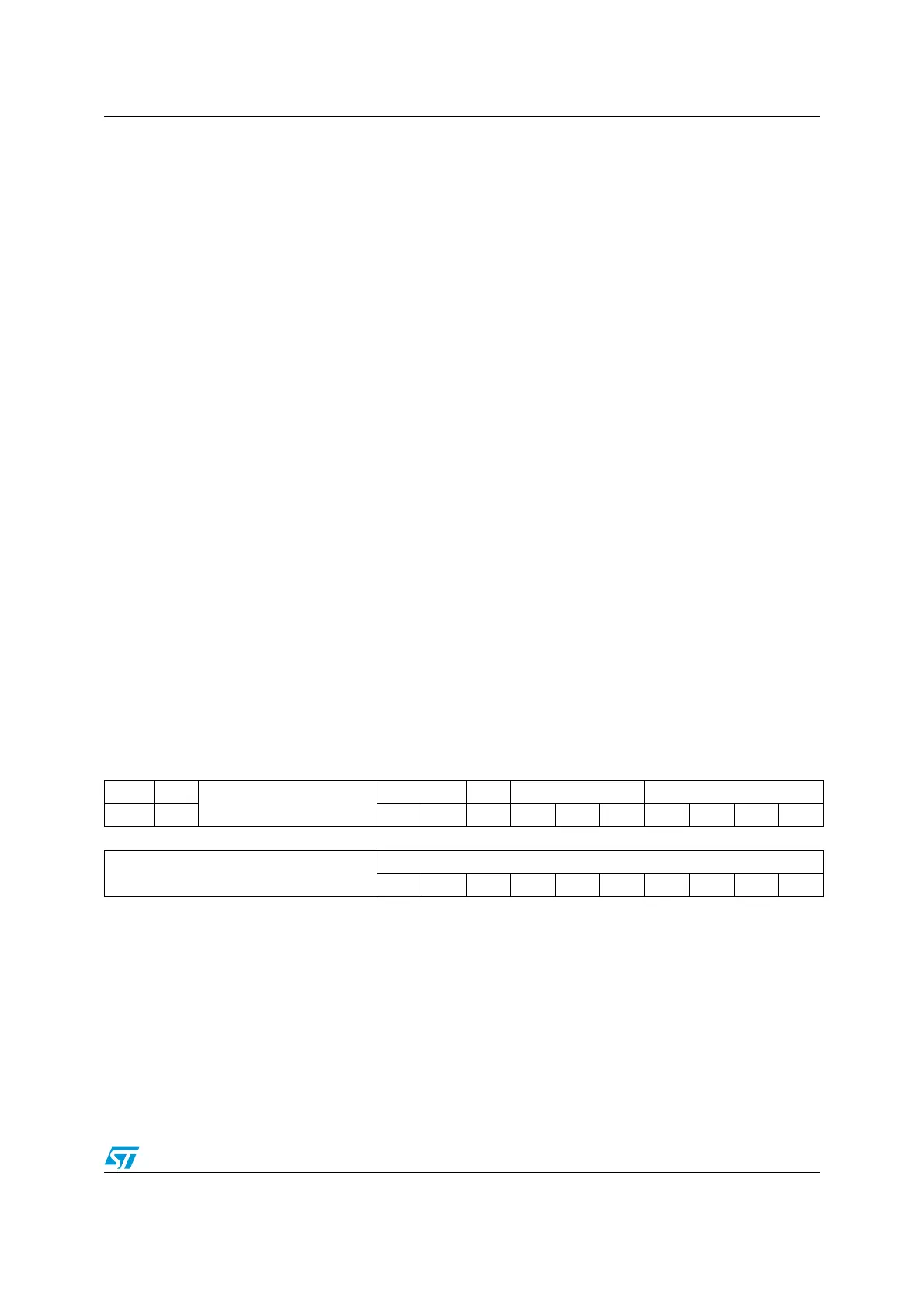
CAN bit timing register (CAN_BTR)
Address offset: 0x1C
Reset value: 0x0123 0000
Note: This register can only be accessed by the software when the CAN hardware is in
initialization mode.
Bits 6:4 LEC[2:0]: Last error code
This field is set by hardware and holds a code which indicates the error condition of the last
error detected on the CAN bus. If a message has been transferred (reception or
transmission) without error, this field will be cleared to ‘0’.
The LEC[2:0] bits can be set to value 0b111 by software. They are updated by hardware to
indicate the current communication status.
000: No Error
001: Stuff Error
010: Form Error
011: Acknowledgment Error
100: Bit recessive Error
101: Bit dominant Error
110: CRC Error
111: Set by software
Bit 3 Reserved, forced by hardware to 0.
Bit 2 BOFF
: Bus-off flag
This bit is set by hardware when it enters the bus-off state. The bus-off state is entered on
TEC overflow, greater than 255, refer to Section 24.7.6 on page 646.
Bit 1 EPVF: Error passive flag
This bit is set by hardware when the Error Passive limit has been reached (Receive Error
Counter or Transmit Error Counter>127).
Bit 0 EWGF
: Error warning flag
This bit is set by hardware when the warning limit has been reached
(Receive Error Counter or Transmit Error Counter≥96).
31 30 29 28 27 26 25 24 23 22 21 20 19 18 17 16
SILM LBKM
Reserved
SJW[1:0] Res. TS2[2:0] TS1[3:0]
rw rw rw rw rw rw rw rw rw rw rw
1514131211109876543210
Reserved
BRP[9:0]
rw rw rw rw rw rw rw rw rw rw
Bit 31 SILM: Silent mode (debug)
0: Normal operation
1: Silent Mode
Bit 30 LBKM
: Loop back mode (debug)
0: Loop Back Mode disabled
1: Loop Back Mode enabled
Bits 29:26 Reserved, forced by hardware to 0.

 Loading...


