RM0090 Rev 18 1659/1749
RM0090 Flexible memory controller (FMC)
1682
Attribute memory space timing registers 2..4 (FMC_PATT2..4)
Address offset: 0x4C + 0x20 * (x – 1), x = 2..4
Reset value: 0xFCFC FCFC
Each FMC_PATTx (x = 2..4) read/write register contains the timing information for PC
Card/CompactFlash or NAND Flash memory bank x. It is used for 8-bit accesses to the
attribute memory space of the PC Card/CompactFlash or to access the NAND Flash for the
last address write access if the timing must differ from that of previous accesses (for
Ready/Busy management, refer to Section 37.6.5: NAND Flash prewait functionality).
Bits 23:16 MEMHOLD[7:0]: Common memory x hold time
For NAND Flash read accesses to the common memory space, these bits define the
number of (HCLK+2) clock cycles during which the address is held after the command is
deasserted (NWE, NOE).
For NAND Flash write accesses to the common memory space, these bits define the
number of HCLK clock cycles during which the data are held after the command is
deasserted (NWE, NOE).
0000 0000: reserved
0000 0001: 1 HCLK cycle for write accesses, 3 HCLK cycles for read accesses
1111 1110: 254 HCLK cycle for write accesses, 256 HCLK cycles for read accesses
1111 1111: Reserved.
Bits 15:8 MEMWAIT[7:0]: Common memory x wait time
Defines the minimum number of HCLK (+1) clock cycles to assert the command (NWE,
NOE), for PC Card/NAND Flash read or write access to common memory space on socket
x. The duration of command assertion is extended if the wait signal (NWAIT) is active (low)
at the end of the programmed value of HCLK:
0000 0000: reserved
0000 0001: 2 HCLK cycles (+ wait cycle introduced by deasserting NWAIT)
1111 1110: 255 HCLK cycles (+ wait cycle introduced by deasserting NWAIT)
1111 1111: Reserved
Bits 7:0 MEMSET[7:0]: Common memory x setup time
Defines the number of HCLK (+1) clock cycles to set up the address before the command
assertion (NWE, NOE), for PC Card/NAND Flash read or write access to common memory
space on socket x:
0000 0000: 1 HCLK cycle
1111 1110: 255 HCLK cycles
1111 1111: Reserved.
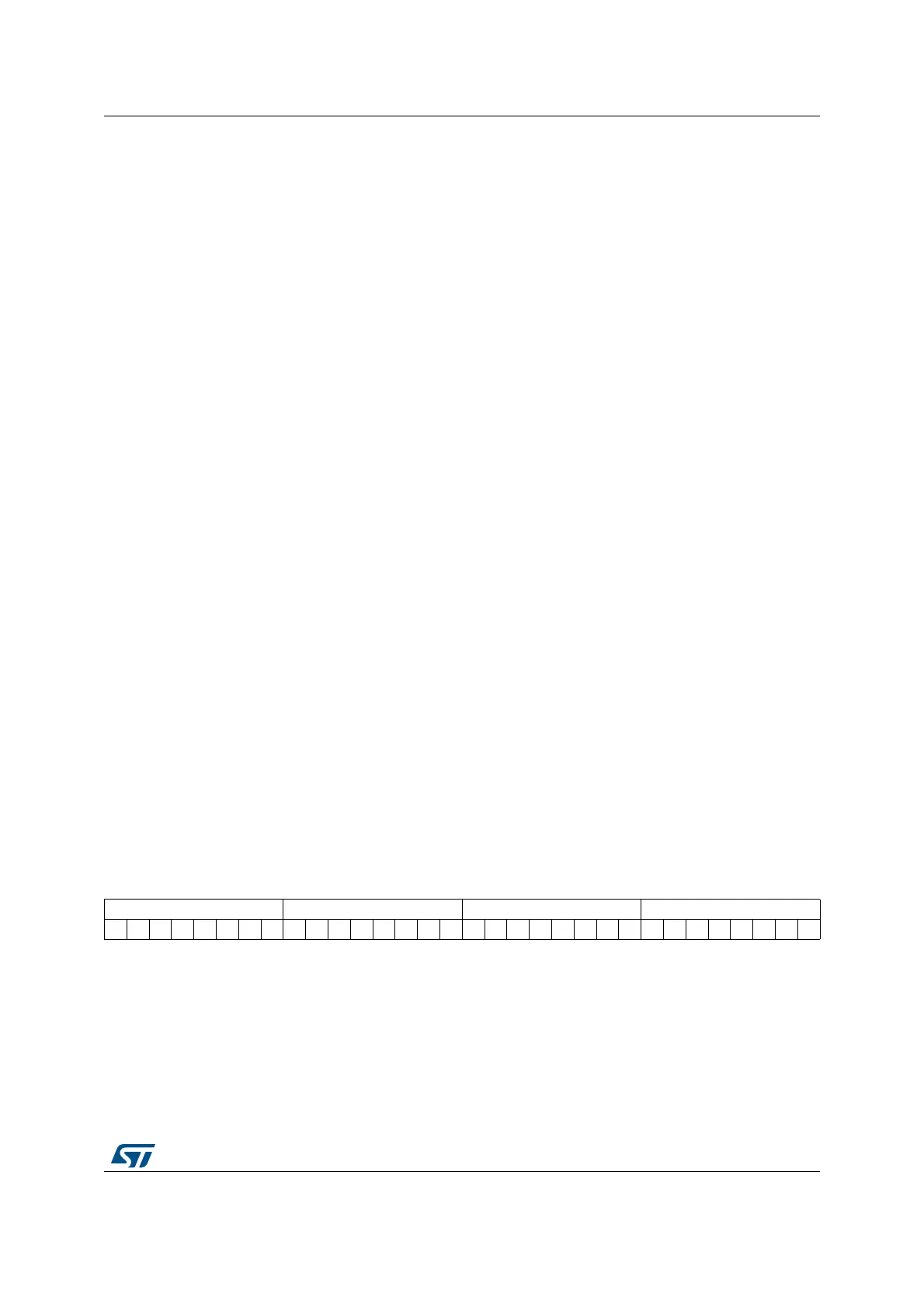
313029282726252423222120191817161514131211109876543210
ATTHIZ[7:0] ATTHOLD[7:0] ATTWAIT[7:0] ATTSET[7:0]
rw rw rw rw rw rw rw rw rw rw rw rw rw rw rw rw rw rw rw rw rw rw rw rw rw rw rw rw rw rw rw rw
Bits 31:24 ATTHIZ[7:0]: Attribute memory x data bus Hi-Z time
Defines the number of HCLK clock cycles during which the data bus is kept in Hi-Z after the
start of a PC CARD/NAND Flash write access to attribute memory space on socket x. Only
valid for write transaction:
0000 0000: 0 HCLK cycle
1111 1110: 255 HCLK cycles
1111 1111: Reserved.