Chapter 6
Adjustment and verification
Trimble S, VX, SPS & RTS Service Manual6 - 98 P/N 57150002, Revision 5.0
F
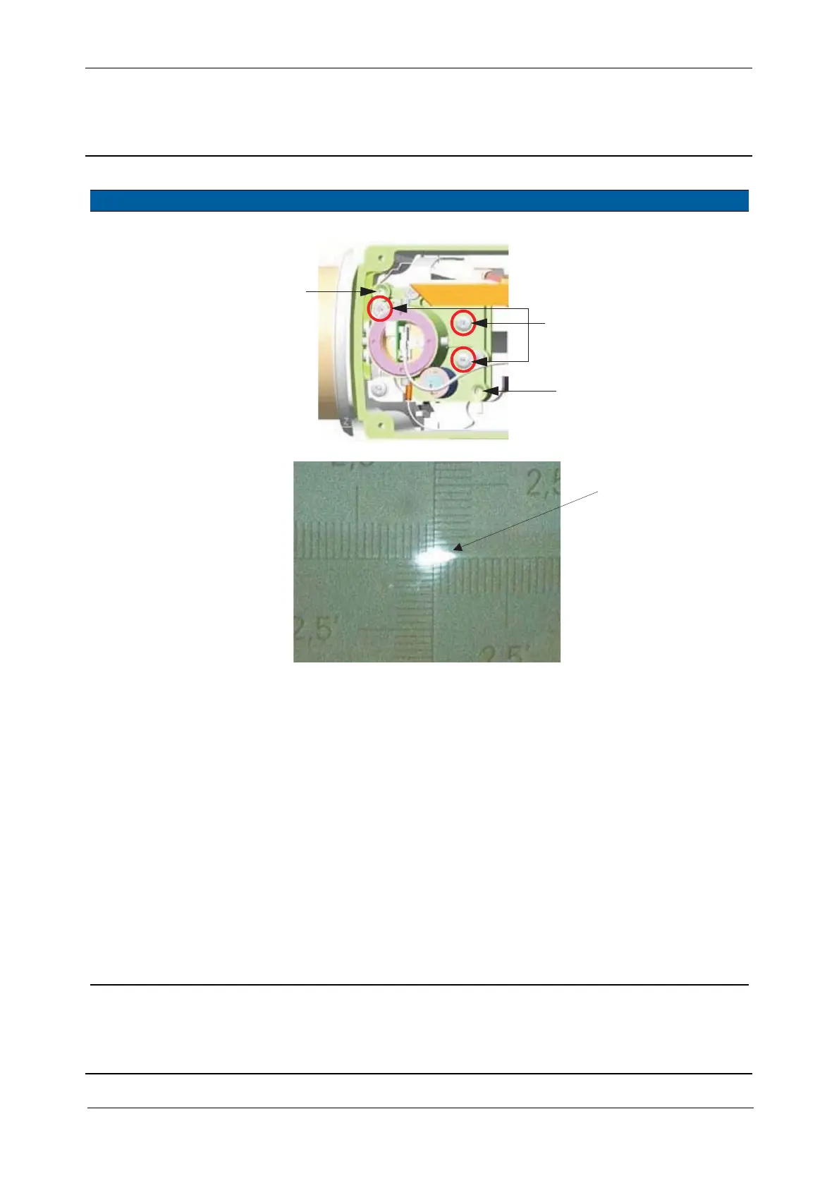
Fig. 6-108 Laser pointer adjustment to infinity and close range
7 Check position of
transmitter beam on
transmitter prism
again.
Follow instructions in step
5.
8 Align transmitter
beam (laser pointer) at
close range (30 meter).
A. Aim to a 30 meter
target.
B. Select
Switch filter
motor HIGH/LOW
check
box.
C. Click Filter motor
HIGH.
D. Adjust the spot to the
target with the vertical
and horizontal
adjustment screws, see
Fig. 6-108 on page 6-
98 .
Deviation from
centre 10“ (1/2
of double line
on instruments
cross-hair).
The evaluation of the
transmitter spot,see
Fig. 6-109 on page 6-
99 has to be done
under dark light
condition by close
observation
(alternatively a
theodolite or
binocular can be used
for observation).
Item Performance Description Result Notes
Do not touch Tracker
Vertical adjustment
(e.g. clockwise down)
Horizontal adjustment
(e.g. clockwise left)
transmitter screws
F
F
Laser spot