Service Parts Disassembly 8-143
9. Release the wiring from the guide just above the Cyan Imaging Motor.
10. Disconnect the Fan connector from the right side of the board.
11. Position the Toner Supply Cams so they are flush with the openings in the frame.
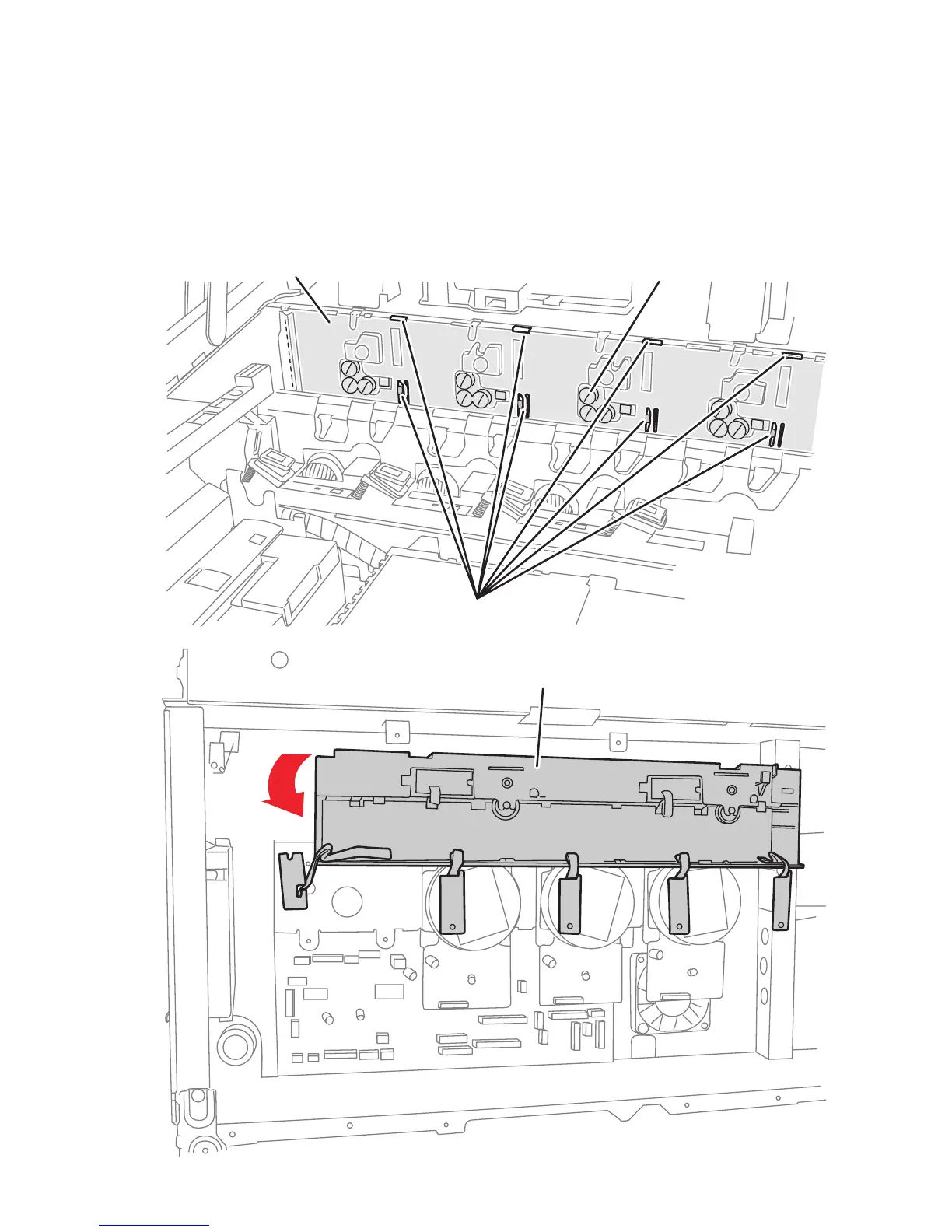
12. Shift the Toner Supply Housing to the left, when viewed from the front, to release
the 4 hooks located next to the grounding contacts.
13. Release the 4 hooks located along the top edge of the housing, and then remove
the housing.
Toner Supply Housing
-
Imaging Unit Sensor Board (behind chassis)
Hooks
s7400-521
Grounding Contact