8-142 Phaser 7400 Color Printer Service Manual
Imaging Unit Sensor Board
The Imaging Unit Sensor Board is held in the Toner Supply Housing. Remove the
housing to facilitate replacement of the board.
Note
A non-captive spring is installed in the Toner Supply Housing just below the
Cyan contacts. Removal of the Toner Supply Housing allows this spring to fall
from its hole.
1. Remove the Rear Cover (page 8-13).
2. Remove the Right Rear Cover (page 8-15).
3. Remove the Card Cage Fan Duct (page 8-114).
4. Remove the Card Cage (page 8-117).
5. Remove the Black Imaging Unit Motor (page 8-105).
6. Release the 2 Toner Motors (page 8-104) from their mounts.
7. Release the Lift Uplink Sensor from the holder next to the Card Cage Fan.
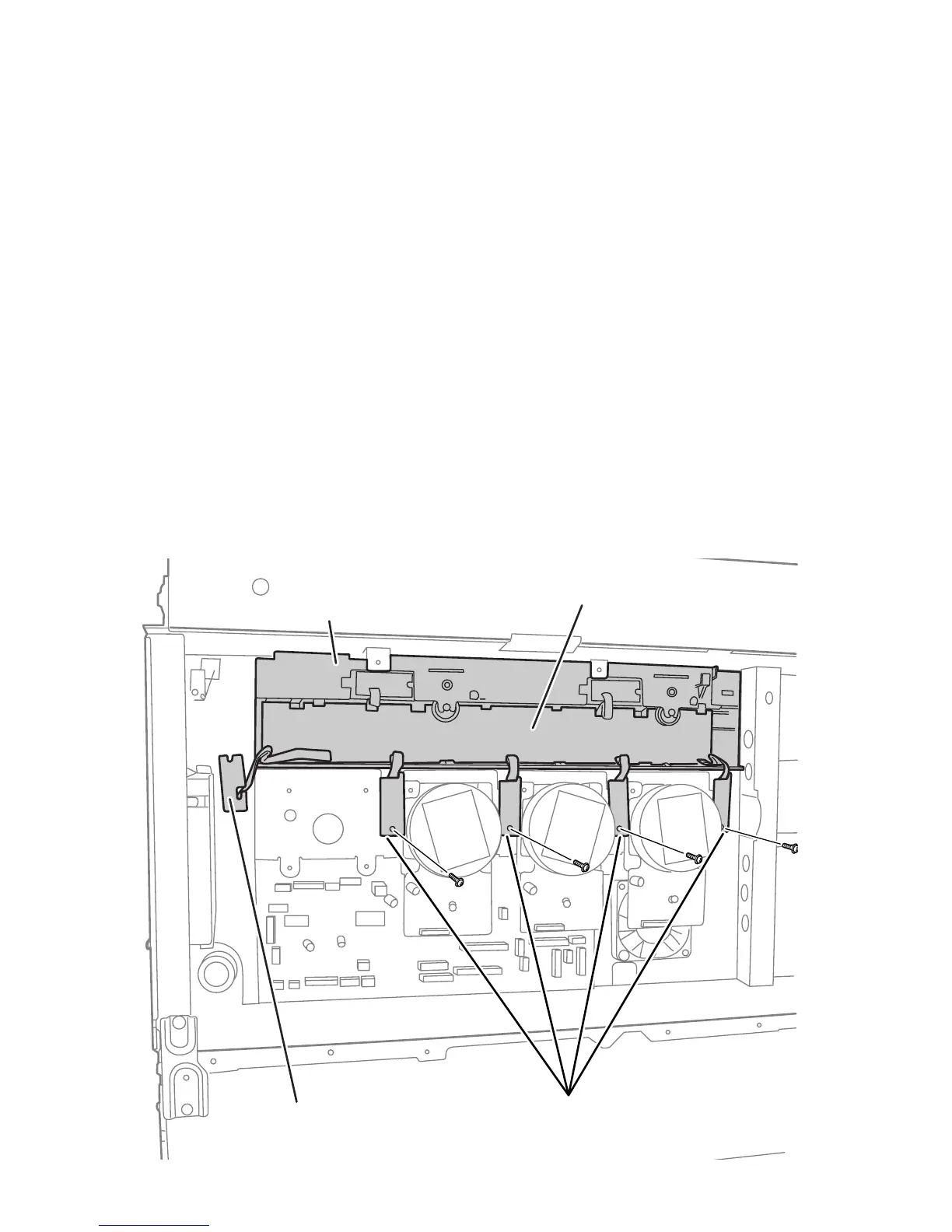
8. Remove 1 (metal, 6 mm) screw on each of the 4 Imaging Unit Drum Phase
Sensors and release the sensors from their retainers.
Imaging Unit Sensor Board
Drum Phase Sensors
Toner Supply Housing
Lift Uplink Sensor