Measurement
371
For how to determine the deviation from a linear phase, see Measuring the
Deviation from a Linear Phase.
Procedure using marker
1. Press Channel Next/Channel Prev keys and Trace Next/Trace prev keys
to activate the trace for which you want to set the electrical delay.
2. Place the active marker in an appropriate position.
3. Press Maker Fctn.
4. Click Marker -> Delay to set the electrical delay to the group delay
value at the position of the active marker (a value smoothed with the
aperture of 20% regardless of the smoothing setting).
Phase offset
Phase offset is a function used to add or subtract a predetermined value
relative to the frequency to and from the trace. Using this function enables
you to simulate the phase offset occurring as a result of, say, adding a
cable.
The phase offset can be specified from - 360 ° to +360 ° .
Using the Phase Offset Function
1. Press Channel Next/Channel Prev keys and Trace Next/Trace prev keys
to activate the trace for which you want to specify the phase offset.
2. Press Scale key.
3. Click Phase Offset, then enter the phase offset ( ° ) in the data entry
area.
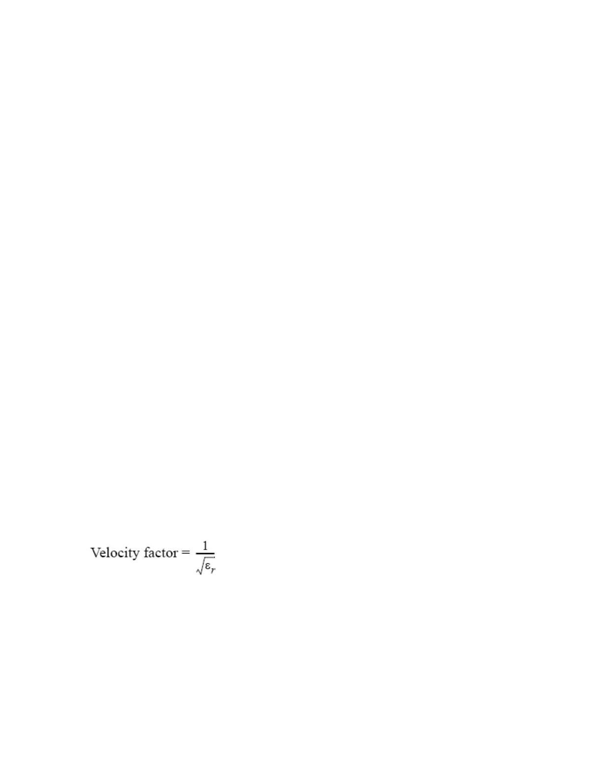
Velocity factor
The velocity factor is the ratio of the propagation velocity of a signal in a
coaxial cable to the propagation velocity of that signal in free space. The
velocity factor for a common cable is about 0.66. The propagation velocity
depends on the dielectric constant (ƒÃ
r
) of the dielectric substance the
cable.
By specifying the velocity factor, you can match the equivalent length (in
meters) appearing in the data entry area to the actual physical length
when using the Electrical Delay or Setting port extensions to specify the
electrical delay (in seconds).
You can define the velocity factor channel by channel.
Using the velocity factor
1. Press Channel Next/Channel Prev keys to activate the channel for
which you want to specify the velocity factor.