E5071C
76
From Firmware revision A.08.10, channel display configuration
of 8×9, 6×12 and 8×12 is added.
Setting Trace Display
Setting the number of traces
Depending on the measurement parameters of the traces displayed for
each channel, the sweep necessary for each channel is executed. For more
information, refer to Sweep Order in Each Channel.
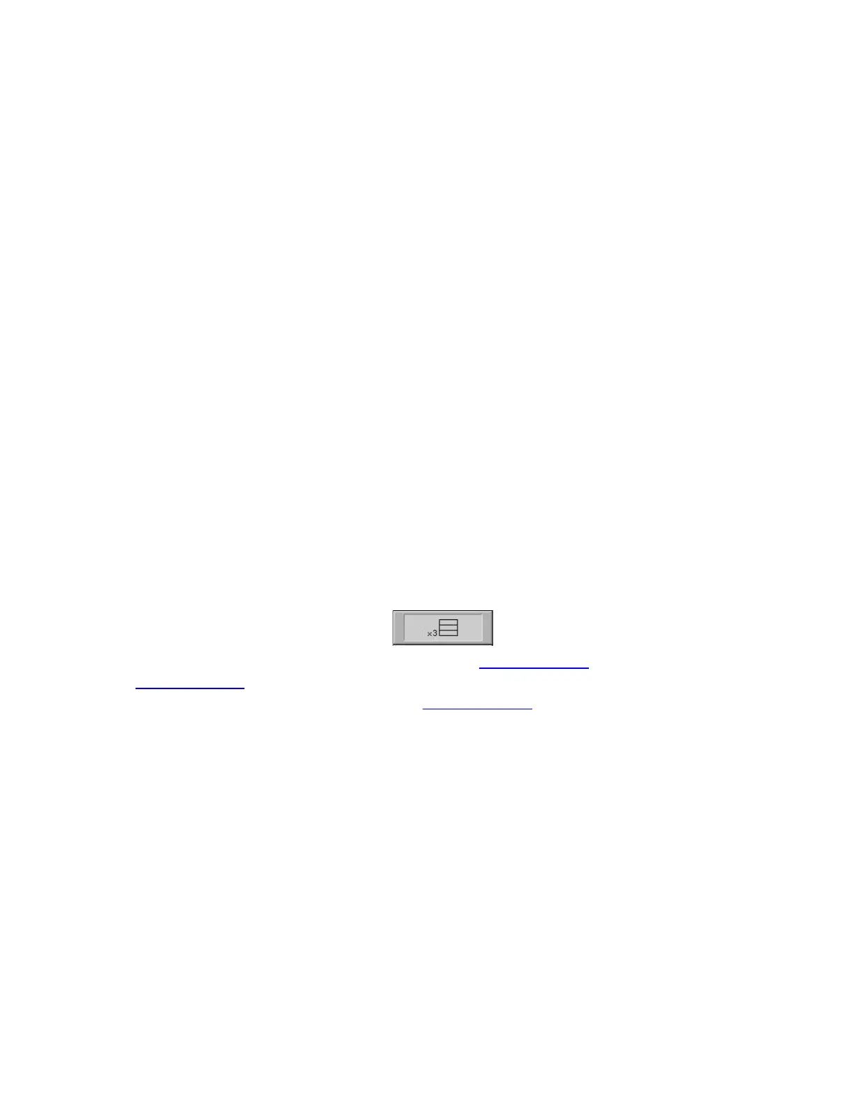
You specify the trace display by setting the number of traces (upper limit
of displayed trace numbers). For example, if you set the number of traces
to 3, traces 1 through 3 are displayed.
The procedure for setting the number of traces is as follows:
1. Press Channel Next or Channel Prev to select the channel for which
you want to set the number of traces.
2. Press Display > Number of Traces.
3. Press the desired softkey to set the number of traces.
Setting trace layout (graph layout)
Traces are laid out and displayed in the order of the trace number from
graph 1 according to the graph layout in the channel window.
You can select the graph layout from the windows layout.
If the number of traces is less than the number of graphs, nothing is
displayed in the remaining area. If the number of traces you set exceeds
the number of graphs, excess traces are superimposed from the first
graph. For example, if you select as the graph layout and set
the number of traces to 5, graph 1 (Gr1 in Graph layout) and graph 2 (Gr2
in Graph layout) display traces 1 and 4 and traces 2 and 5, respectively, by
superimposing, and graph 3 (Gr3 in Graph layout) displays only trace 3 as
shown in the figure below.