E5071C
1094
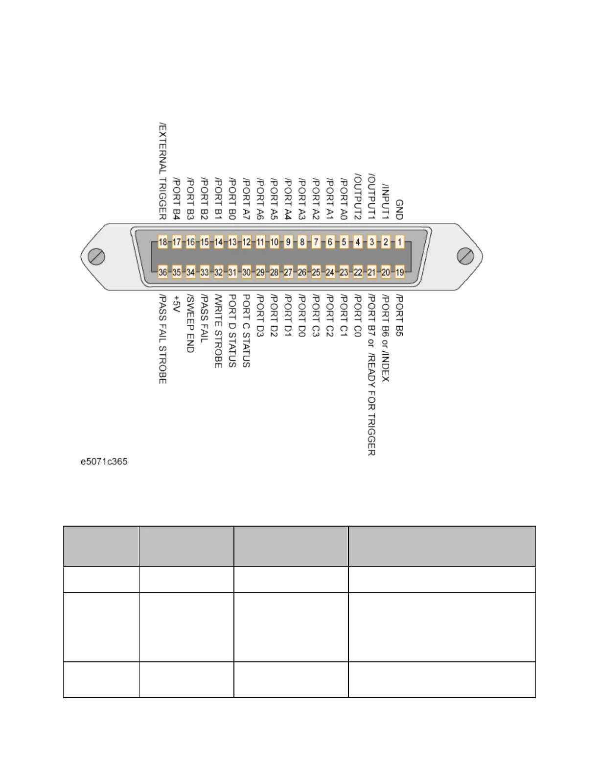
I/O Signal Pin Layout and Description
The layout of the I/O signal pins on the handler interface connector and its
description are shown below.
A slash (/) symbol preceding signal names means that they are negative
logic (active low).
Pin
number
Signal
name
Input/Output Description
1 GND N/A Ground.
2 /INPUT1 Input
When this port receives a
negative pulse, /OUTPUT1
and /OUTPUT2 are
changed to the Low level.
3 /OUTPUT1 Output
Changes to the Low level
when /INPUT1 receives a