6. EM GUI orientation
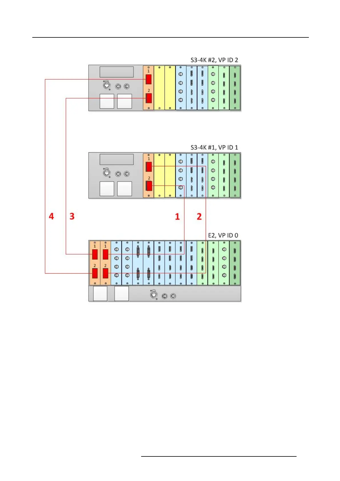
See image 6-32for an example of the cabling between an E2 unit and two S3-4K units.
Image 6-32
Cabling between an E2 unit and two S3–4K units
Event Master Configuration
1. Start the Event M aster Toolset version 4.2 or higher.
2. Make sure that the E2 and the S3–4K units are discovered on the network and that they have different Unit IDs.
3. DroptheE2intheGUI.
4. Drop the S3–4K #1 in the GUI.
You will be presented the option to add as a new system, add as a master, or add as a slave. An S3–4K can be added as a
Master or Slave to an E2.
5. Select either add as a master or add as a slave.
6. Drop the S3–4K #2 in the GUI.
You will be presented the option to add as a new system, add as a master, or add as a slave. An S3–4K can be added as a
Master or Slave to an E2.
7. Select either add as a master or add as a slave.
8. (Optional) At this point it is suggested that you select and name appropriately each unit so that you can identify it in your setup.
How to L ink an E2 Unit, an S3-4K Unit, and four EX Units
Each E2 comes equipped with two Link cards, alway s located in s lots 1 and 2. Each S3–4K has a single Link card in slot 1. Link
cards are identified by a yellow stripe at the top. Eac h EX has two Link sockets. Make sure to use the locking m echanism and then
push each cable until it locks in place.
R5905948 EVENT MASTER DEVICES 17/07/2017
143