6. EM GUI orientation
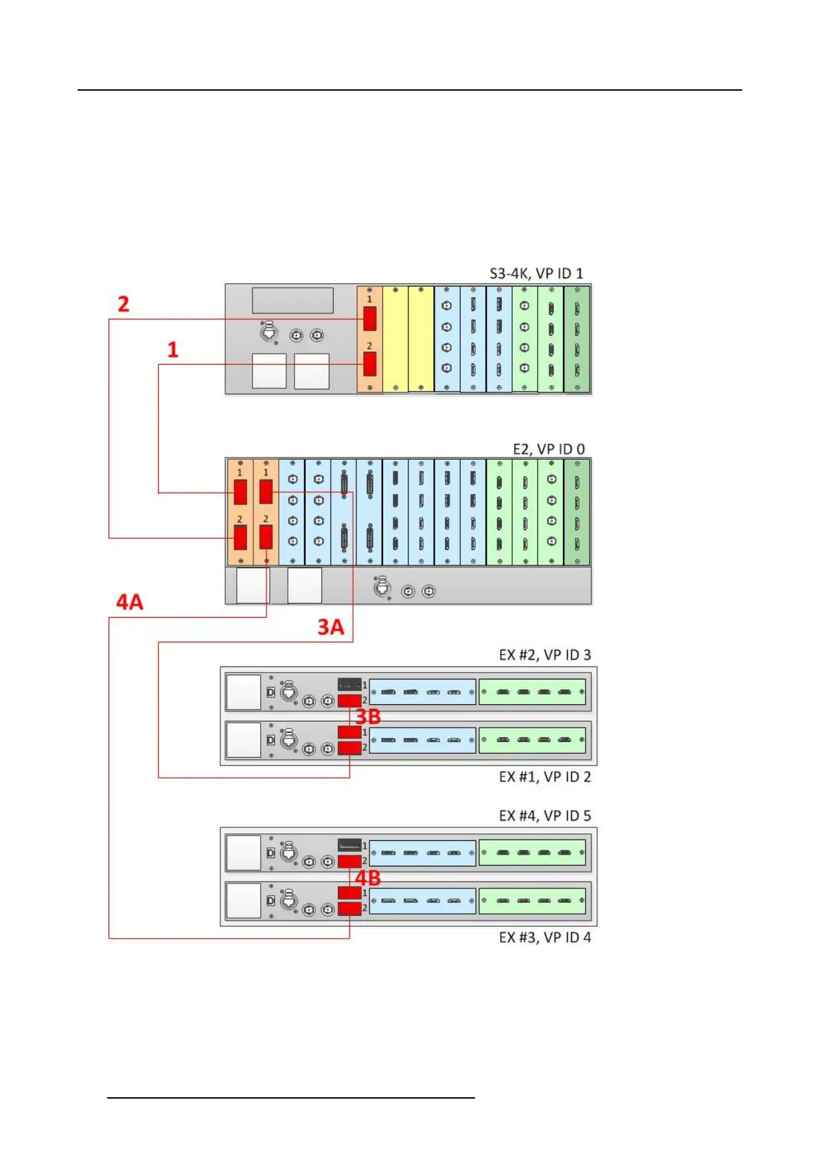
Connect the Link cables provided with each unit between the Link connectors as follows:
• E2 VP ID 0, Link Card slot 1, Link 1 >> S3 VP ID 1, Link Card slot 1, Link 2
• E2 VP ID 0, Link Card slot 1, Link 2 >> S3 VP ID 1, Link Card slot 1, Link 1
• E2 VP ID 0, Link Card slot 2, Link 1 >> EX VP ID 2, Link 2
• EXVPID2,Link1>>EXVPID3,Link2
• E2 VP ID 0, Link Card slot 2, Link 2 >> EX VP ID 4, Link 2
• EXVPID4,Link1>>EXVPID5,Link2
See image 6-33 for an example of the cab ling between a n E2 unit, an S3-4K unit, and four EX units.
Image 6-33
Cabling between an E2 unit, an S 3–4K unit, and four EX units
Event Master Configuration
1. Start the Event M aster Toolset version 4.1 or higher.
2. Make sure that the E2, the S3–4K, an d the EX are dis covered on the network and that they have different Unit ID s.
3. DroptheE2intheGUI.
144
R5905948 EVENT MASTER DEVICES 17/07/2017