EZ-USB FX3 Technical Reference Manual, Document Number: 001-76074 Rev. *F 107
Universal Serial Bus (USB)
6.9.10 Functional Description
6.9.10.1 Embedded Host
The FX3 USB 2.0 embedded host operates similar to an EHCI host when in high-speed mode and like an OHCI host when in
low- or full-speed mode, but the implementation does not follow the fields of the data structures specified in the EHCI/OHCI
spec.
At the lowest level, incoming and outgoing data are managed by the DMA block. All USB transfer types, namely control, bulk,
isochronous and interrupt; are handled in a similar way by the DMA block. Refer to the FX3 DMA Subsystem chapter on
page 58 to learn how the DMA descriptor and socket data structures are organized and used.
As a USB host, data traffic is initiated by configuring the appropriate entries in the scheduler memory areas inside the USB
2.0 host controller. The USB 2.0 host controller hardware scans the scheduler memory for valid entries that contain the active
endpoint configurations and schedules data on the bus accordingly.
6.9.10.2 Scheduler Memory
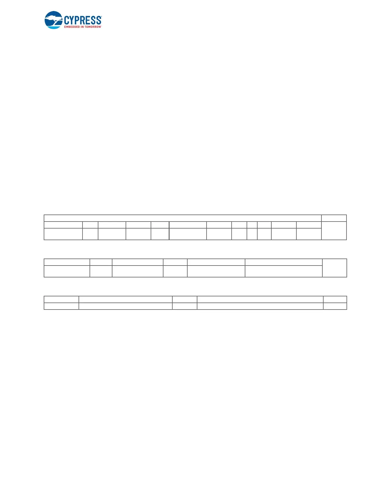
Figure 6-3 shows the bit field of a scheduler entry data structure positioned in the scheduler memory. Definitions of the bit
fields are provided in the register definition section. Each scheduler entry requires three 32-bit words, 12 bytes of memory.
There are 32 entries for EP, which sums the total available memory of 384 bytes.
Figure 6-3. Scheduler Memory Entry
6.9.10.2.1 Scheduler Memory Organization
A host controller driver has the option to add or remove entries in the list. Two copies of the scheduler memory table are
provided so that firmware can first update the table and then make it active.
Active scheduler entries in the scheduler memory form the execution list for the host controller hardware. The execution list is
broken into the periodic list which services periodic (isochronous and interrupt) endpoints and the asynchronous list which
services bulk and control endpoints.
Each scheduler memory area contains a periodic list and an asynchronous/non-periodic list. Figure 6-4 shows how the list is
organized in high-speed mode, and low- or full-speed mode. The periodic list pointer points to the first entry in the periodic list.
It always starts from the lowest address of each scheduler memory.
Memory bits Addr
31:24 23 22:19 18:17 16 15:14 13:10 9 8 7 6:5 4:0
I
S_mask PING RL MULT
ISO_EP
M
CERR NakCnt Halt T
ZLPE
N
EPT EPND
31:30 29 28:27 26:19 18:11 10:0
I+1
EP0_code
Bypass_e
rr
MMULT Resp_rate Polling_rate Max_Packet_size
31:25 24:17 16 15:0 I+2
Reserved ioc_rate trns_mode Total Byte Count

 Loading...


