EZ-USB FX3 Technical Reference Manual, Document Number: 001-76074 Rev. *F 156
General Programmable Interface II (GPIF II)
7.13.1 Alpha Values
Control outputs from the GPIF II state machine can be classified into early outputs and delayed/normal outputs. The early
outputs have a shorter output latency than the delayed outputs. This is achieved by making their values available to the GPIF
II hardware one cycle earlier than all the other state information. The early output signals from GPIF II are called "Alphas,"
and their total number is limited to eight signals.
As the values for the Alpha class outputs are specified and interpreted differently by the GPIF II hardware, the initial values for
these signals also need to be specified outside the state machine description. The initial Alpha values that a GPIF II design
needs to have are generated in the form of a <PROJECT_NAME>_ALPHA_START macro in the GPIF II configuration header
file. This value is expected to be passed as the initial Alpha parameter to the CyU3PGpifSMStart() API after the
CyU3PGpifLoad() API has been called.
7.14 GPIF II Read and Write over Registers
IN_DATAx_VALID and OUT_DATAx_VALID (where "x" varies from 0 to 3) are the bit fields of the GPIF_DATA_CTRL register.
IN_DATAx_VALID is set high by the GPIF II hardware when data is written to the GPIF_INGRESS_DATA register
corresponding to socket x using the IN_DATA action in the GPIF II state machine. This will be cleared by the FX3 firmware
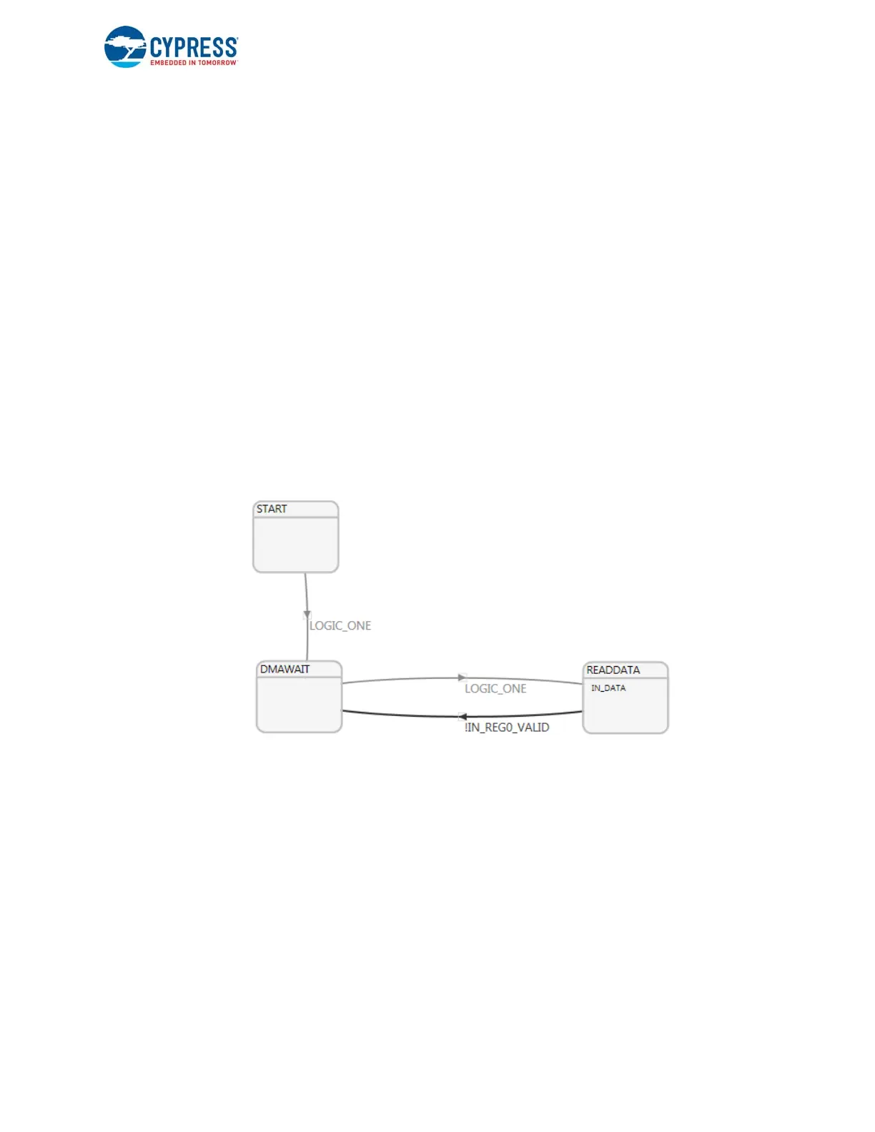
when the data in the GPIF_INGRESS_DATA register is read using the CyU3PGpifReadDataWords function. Figure 7-42
shows the GPIF II state machine that reads data from the data bus into the FX3 over the GPIF II register. It will read all ones
if no device is connected to the FX3 GPIF II.
Figure 7-42. GPIF II State Machine to Read Data from the Data Bus
The IN_DATA action reads the data available on the data bus and places it in the GPIF INGRESS register corresponding to
socket 0. IN_DATA action settings are shown in Figure 7-43.

 Loading...


