EZ-USB FX3 Technical Reference Manual, Document Number: 001-76074 Rev. *F 38
FX3 CPU Subsystem
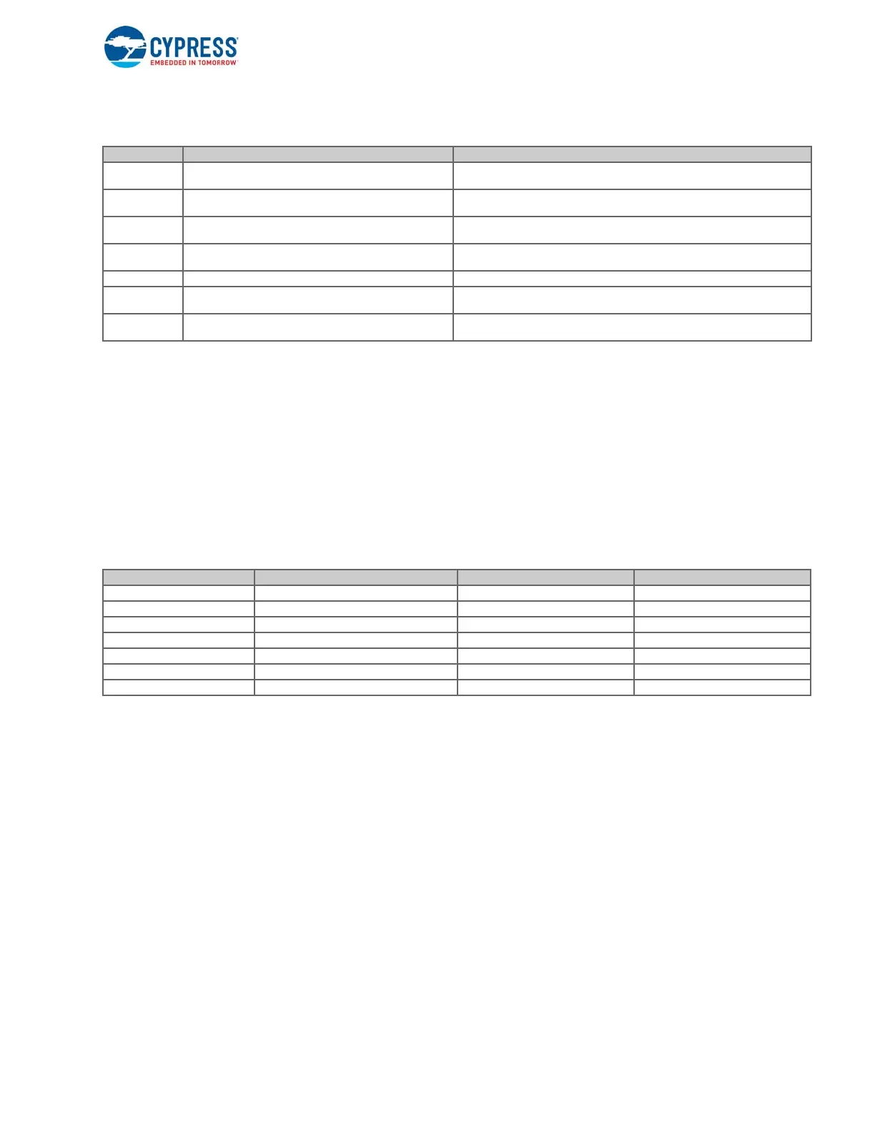
Table 2-2. ARM9 Processor Registers
2.3.1.3 Exception Vectors
The exception vectors that serve as the entry point for each of the exception modes are stored in a table in the main system
memory. These vectors can be placed at one of two addresses: 0x00000000 or 0xFFFF0000. The selection of the exception
vector table location is based on the ARM standard system control coprocessor (CP15) configuration.
As shown in Table 2-3, the normal exception vectors are located in the address range from 0x0 onward, which falls in the
instruction TCM (ITCM) region. The high exception vectors are located in the address range from 0xFFFF0000, which is part
of the BootROM on the FX3 device. As the high-exception vectors are hard-wired to vector to the bootloader on the FX3
device, the normal (user-definable) exception vectors are used when running user applications.
Table 2-3. ARM Exception Vector Locations
The following code snippet shows the procedure to move the exception vectors to address 0x0. This step is done by the FX3
firmware library as part of device initialization.
MRC p15, 0, r1, c1, c0, 0/* Read the CP15 register value */
MOV r2, #0xFFFFDFFF
AND r1, r1, r2/* Mask off the vector location bit. */
MCR p15, 0, r1, c1, c0, 0/* Write back to CP15 register. */
2.3.1.4 MMU
The MMU in the ARM926EJ-S processor is an ARM architecture v5 implementation, which supports the virtual memory
features required by standard embedded operating systems. The MMU uses a set of two-level page tables located in the
main memory to control the address translation, permission checks, and so on.
The data cache on the ARM core can be enabled only if the MMU is enabled. However, most FX3 designs do not use any
secondary storage and do not need a virtual memory system. FX3 provides a fixed set of page tables that maps each physical
address to the equivalent virtual address.
Register Description Attributes
R0-R7 General-purpose registers
These are not banked registers, which means that the same physical register is
used in all processor modes.
R8-R12 General-purpose registers
Two copies of these registers exist. One copy is used only in FIQ mode, and the
other copy is used in all other processor modes.
R13 Stack pointer (SP)
Six copies of this register exist. The user and system modes share one register,
and all other modes have their own SP register.
R14
Link register (LR), used to hold return address when execut-
ing branch instructions
Six copies of this register exist. The user and system modes share one register,
and all other modes have their own LR register.
R15 Used to read/write the program counter Single register that is used across all processor modes.
CPSR
Current program status register, provides status flags,
global interrupt enable control, and so on
The CPSR register reflects the current program status in each of the processor
modes.
SPSR
Saved program status register, provides saved program sta-
tus for each exception mode
Separate copies of this register exist for each of the FIQ, IRQ, supervisor, abort,
and undefined modes.
Exception Type Processor Mode Exception Vector 1 (normal) Exception Vector 2 (high)
Reset Supervisor 0x00000000 0xFFFF0000
Undefined instruction Undefined 0x00000004 0xFFFF0004
Software interrupt (SWI) Supervisor 0x00000008 0xFFFF0008
Prefetch abort Abort 0x0000000C 0xFFFF000C
Data abort Abort 0x00000010 0xFFFF0010
IRQ (interrupt) IRQ 0x00000018 0xFFFF0018
FIQ (interrupt) FIQ 0x0000001C 0xFFFF001C

 Loading...


