EZ-USB FX3 Technical Reference Manual, Document Number: 001-76074 Rev. *F 33
Introduction to EZ-USB FX3
Refer to the application note AN76405 - EZ-USB FX3 Boot Options.
In addition to these FX3 boot options, FX3S supports the following:
■ Boot from eMMC (Storage port)
■ Boot from PMMC (Processor port)
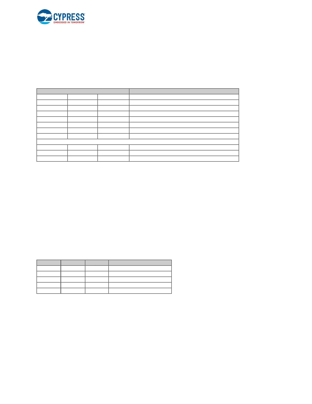
Table 1-4. Boot Mode Selection Based on PMODE Pins
Z = Pin is floating; left unconnected.
1.4.11 Clocking
FX3 allows either connecting a crystal between the XTALIN and XTALOUT pins or connecting an external clock to the CLKIN
pin. The XTALIN, XTALOUT, CLKIN, and CLKIN_32 pins can be left unconnected if they are not used.
The crystal frequency supported is 19.2 MHz, while the external clock frequencies supported are 19.2, 26, 38.4, and 52 MHz.
FX3 has an on-chip oscillator circuit that uses an external 19.2-MHz (±100 ppm) crystal (when the crystal option is used).
Refer to the application note AN70707 - EZ-USB FX3/FX3S Hardware Design Guidelines and Schematic Checklist for
guidelines on crystal selection. An appropriate load capacitance is required with a crystal. The FSLC[2:0] pins must be
configured appropriately to select the crystal- or clock-frequency option. The configuration options are listed in Table 1-4.
Table 1-5. Crystal and Clock Frequency Selection
Clock inputs to FX3 must meet the phase noise and jitter requirements specified in the EZ-USB FX3 datasheet.
PMODE[2:0] Pins Boot Option
PMODE[2] PMODE[1] PMODE[0]
Z 0 0 Sync ADMUX (16-bit)
Z 0 1 Async ADMUX (16-bit)
Z 0 Z Async SRAM (16-bit)
Z 1 1 USB Boot
1ZZ I2C
Z 1 Z I2C; on failure, USB Boot is enabled
0 Z 1 SPI; on failure, USB Boot is enabled
FX3S Specific Boot Options
Z 1 0 PMMC Legacy
0 0 0 S0-port (eMMC); On Failure, USB Boot is enabled
1 0 0 S0-port (eMMC)
FSLC[2] FSLC[1] FSLC[0] Crystal/Clock Frequency
0 0 0 19.2-MHz Crystal
1 0 0 19.2-MHz Input CLK
1 0 1 26-MHz Input CLK
1 1 0 38.4-MHz Input CLK
1 1 1 52-MHz input CLK

 Loading...


