EZ-USB FX3 Technical Reference Manual, Document Number: 001-76074 Rev. *F 220
Storage Ports
9.6 FX3S-Specific Features
9.6.1 Card Insertion and Removal Detection Mechanism
FX3S supports the two-card insertion and removal detection mechanisms.
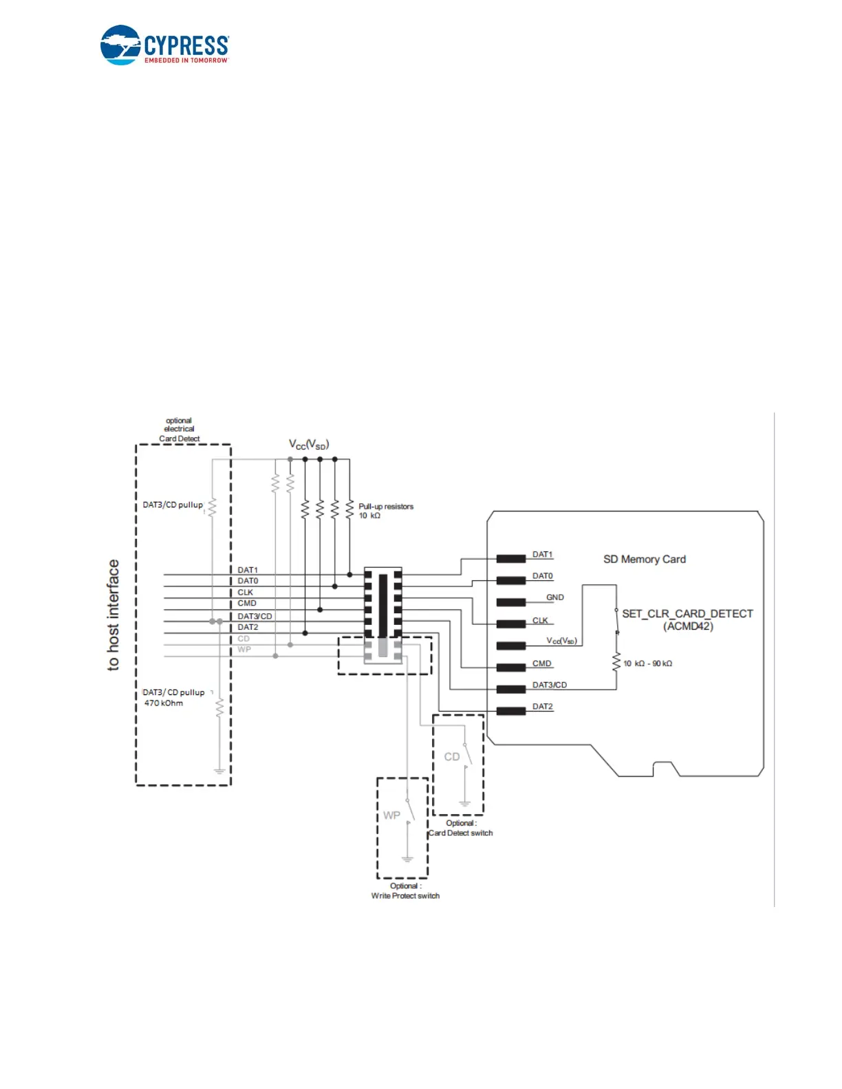
■ Use of SD_D[3] data: This signal must have an external 470-k pull-down resistor connected to SD_D[3]. SD cards have
an internal 10-k pull-up resistor. When the card is inserted or removed from the SD/MMC connector, the voltage level at
the SD_D[3] pin changes and triggers an interrupt to the CPU.
■ Use of the S0/S1_INS pin: Some SD/MMC connectors include a microswitch for card insertion/removal detection. This
microswitch can be connected to S0/S1_INS. When the card is inserted or removed from the SD/MMC connector, it turns
the microswitch on and off. This changes the voltage level at the pin that triggers the interrupt to the CPU. S0/ S1_INS
stays high or floating when card is not inserted and goes low when card is inserted. The card-detect microswitch polarity
is assumed to be the same as the write-protect microswitch polarity. A low indicates that the card is inserted. This S0/
S1_INS pin is shared between the two S-ports. Register configuration determines which port gets to use the pin. This pin
is mapped to the VIO2 power domain (see Ta b l e 9- 1 ); if S0 and S1 are at different voltage levels, the pin cannot be used
as S1_INS. Figure 9-11 depicts this mechanism.
Figure 9-11. Card Detection Using GPIO

 Loading...


