EZ-USB FX3 Technical Reference Manual, Document Number: 001-76074 Rev. *F 143
General Programmable Interface II (GPIF II)
Figure 7-24. GPIF II Designer (Transitions Between Actions)
7.6.4 Add a Transition Equation
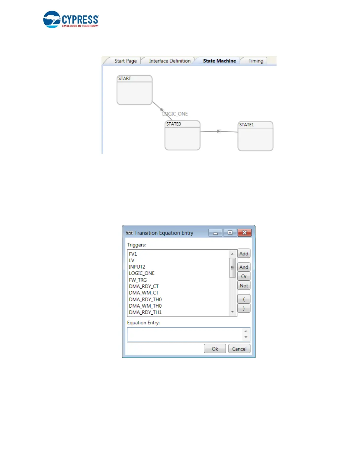
Bring the cursor to point to the transition line. Double-click on the line to open the Transition Equation Entry dialog box. All
available triggers to form a transition equation are displayed as a selectable list. Select the trigger and add to the Equation
Entry using the Add button. Use the necessary Boolean expression notations from the buttons on the left of the dialog box.
Alternatively, you can type the equation directly in the Equation Entry box to enter the Boolean expression. Click OK after
entering the equation. The window that pops up to enter the transition equation is shown in the figure below.
Figure 7-25. GPIF II Designer (Adding a Transition Equation)
7.6.5 Set State Properties
Position the mouse cursor inside a state graphic. Right-click to display the State menu. Select Settings from the menu to open
the State Settings dialog box. Every state can be associated with a name using an alphanumeric string. Macros that map the
state names to the state IDs generated by the tool are generated by the tool as part of the header generation.
The Repeat Count property indicates the number of clock cycles to continue inside the state before evaluating any outgoing
transition equation.
 Loading...


