EZ-USB FX3 Technical Reference Manual, Document Number: 001-76074 Rev. *F 43
FX3 CPU Subsystem
Suspend mode: This applies to both the L1 and L2 modes of the FX3 device. The clock to the CPU is gated in this mode,
and the CPU is placed in the wait for interrupt state. Firmware execution resumes from the next instruction, once the device
wakes from the L1/L2 mode.
Standby mode: This applies to the L3 mode of the FX3 device. The CPU is powered down, while the program RAM content
is retained. Firmware execution starts from the reset vector once the device wakes from the L3 mode.
2.3.1.11 Timers
The ARM CPU does not have any associated timer blocks. The FX3 device provides a pair of general-purpose timers that can
also provide the watchdog functionality. These timers are provided as part of the Global Control block on the FX3 device.
These timers operate on a 32-kHz input clock and can be configured in one of the free running counter, timer with interrupt, or
watchdog reset modes.
Note: If the system provides a clock input through the CLKIN_32 pin of the FX3 device, the timer uses this clock. If not, the
32-kHz clock is derived from the system clock, which runs at about 200 MHz.
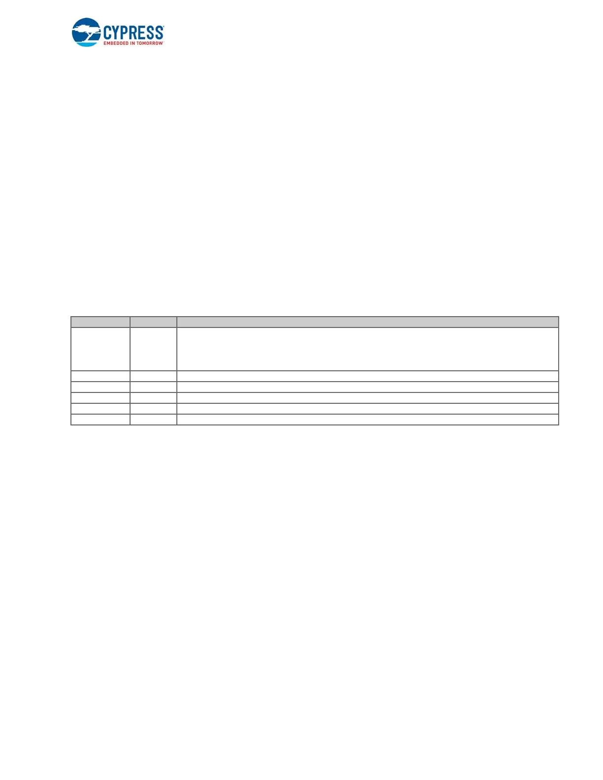
The WATCHDOG_CS register in the GCTL block controls the operation of these timers. The relevant bits in this register are
shown in Ta bl e 2 - 5 .
Table 2-5. Watchdog Timer Control Register
The actual counter values for the timers are stored in the WATCHDOG_TIMER0 and WATCHDOG_TIMER1 registers. When
the timer is configured in reset mode, the firmware is expected to restore this register to its initial value before the counter limit
(lowest BITS bits getting set) is reached.
Hint: As a single interrupt vector is used for both timers, the ISR needs to check the INTR bits in the WATCHDOG_CS register
to identify the timer that triggered the interrupt.
Field Name Bit Range Description
MODE0 1:0
0-Free running mode; counter wraps around after reaching 0xFFFFFFFF.
1-Interrupt mode; raises WATCHDOG_TIMER interrupt when lowest significant BITS0 bits of the counter are cleared
2-Reset mode; resets the FX3 when lowest significant BITS0 bits of the counter are cleared
3-Disabled
INTR0 2 Interrupt status for timer 0
BITS0 7:3 Number of bits to be considered when checking for counter limit
MODE1 9:8 Timer mode for timer 1
INTR1 10 Interrupt status for timer 1
BITS1 15:11 Number of bits to be considered when checking for counter limit

 Loading...


