EZ-USB FX3 Technical Reference Manual, Document Number: 001-76074 Rev. *F 133
General Programmable Interface II (GPIF II)
7.4.2 Triggers
Triggers are signals that cause state transitions to occur. They can be:
External: Control signals driven by the external device
Internal: Internal signals asserted due to hardware or firmware events
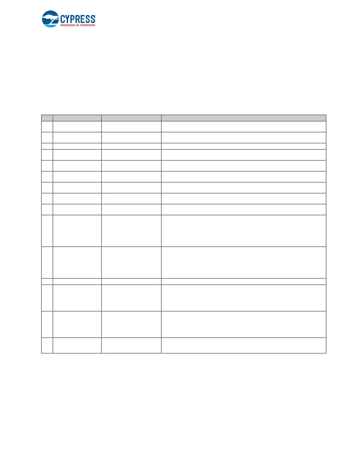
Table 7-3 captures events generated as a result of the GPIF II actions.
Table 7-3. Event Generated by GPIF II Actions
7.4.3 Transition Conditions
Transition conditions determine the transition out of a state and into another. The transition conditions are Boolean logic
functions of the trigger signals. A simple example of actions, triggers, and transition conditions is shown in Figure 7-17, where
the three GPIF II states are IDLE, READ, and WRITE. No actions are asserted in the IDLE state. The CE, RE, and WE
signals are the trigger signals. They are the control input signals to GPIF II and are driven by an external device. The
transition conditions are formed with these signals. The left transition condition is (!CE&&!RE) (a read operation), and the right
No. Event Action Causing the Event Description
1 Input signal name None; this is an external event
The name associated with any GPIO configured as an input can be used as a trigger in a
transition equation.
2 FW_TRG Firmware application
This trigger can be generated from the firmware using the firmware API
CyU3PGpifControlSWInput().
3 INTR_PENDING Interrupt to CPU This is true only when the CPU/host has yet to read the previously raised interrupt.
4 CTRL_CNT_HIT COUNT_CTRL
This trigger is true when the count specified is reached. It is generated as a result of the
COUNT_CTRL action.
5 ADDR_CNT_HIT COUNT_ADDR
This trigger is true when the count specified is reached. It is generated as a result of
COUNT_ADDR action.
7 DATA_CNT_HIT COUNT_DATA
This trigger is true when the count specified is reached. It is generated as a result of
COUNT_DATA action
8 CTRL_CMP_MATCH CMP_CTRL
This trigger is true when the control pattern and mask match the current GPIO. It is gener-
ated only when the CMP_CTRL action is specified in the parent state.
9 DATA_CMP_MATCH CMP_DATA
This trigger is true when the data pattern and mask match the current data. It is generated
only when the CMP_DATA action is specified in the parent state.
10 ADDR_CMP_MATCH CMP_ADDR
This trigger is true when the address pattern and mask match the current address read. It is
generated only when the CMP_ADDR action is specified in the parent state.
11
DMA_RDY_CT,
DMA_RDY_TH0,
DMA_RDY_TH1,
DMA_RDY_TH2,
DMA_RDY_TH3
IN_DATA
DR_DATA
This trigger is true when the DMA is ready to send or receive data.
12
DMA_WM_CT,
DMA_WM_TH0,
DMA_WM_TH1,
DMA_WM_TH2,
DMA_WM_TH3
IN_DATA
This trigger is true when the active DMA thread crosses the transferred data above the
watermark.
13 DMA_RDY_ADDR DR_ADDR This trigger is true when the DMA is ready to send or receive an address.
14
IN_REG_CR_VALID,
IN_REG0_VALID,
IN_REG1_VALID,
IN_REG2_VALID,
IN_REG3_VALID
IN_DATA
This trigger is true when the data in the input register (INGRESS_DATA_REGISTER) is
valid. It is set when GPIF II writes data into the INGRESS_DATA_REGISTER using the
IN_DATA action. It is cleared by the firmware by setting the IN_DATA_VALID field in the
GPIF_DATA_CTRL register.
15
OUT_REG_CT_VALID,
OUT_REG0_VALID,
OUT_REG1_VALID,
OUT_REG2_VALID,
OUT_REG3_VALID
DR_DATA
This trigger is true when the data in the output register (EGRESS_DATA_REGISTER) is
valid. The firmware needs to enable this trigger by setting the EG_DATA_VALID bit in the
GPIF_DATA_CTRL register. This trigger will be cleared when the data in the register has
been transmitted by the GPIF II as a result of the DR_DATA action.
16 OUT_ADDR_VALID DR_ADDR
This trigger is true when the address in the output register
(EGRESS_ADDRESS_REGISTER) is valid. It is done when the firmware sets the
EG_ADDR_VALID bit in the GPIF_DATA_CTRL register.

 Loading...


