EZ-USB FX3 Technical Reference Manual, Document Number: 001-76074 Rev. *F 164
General Programmable Interface II (GPIF II)
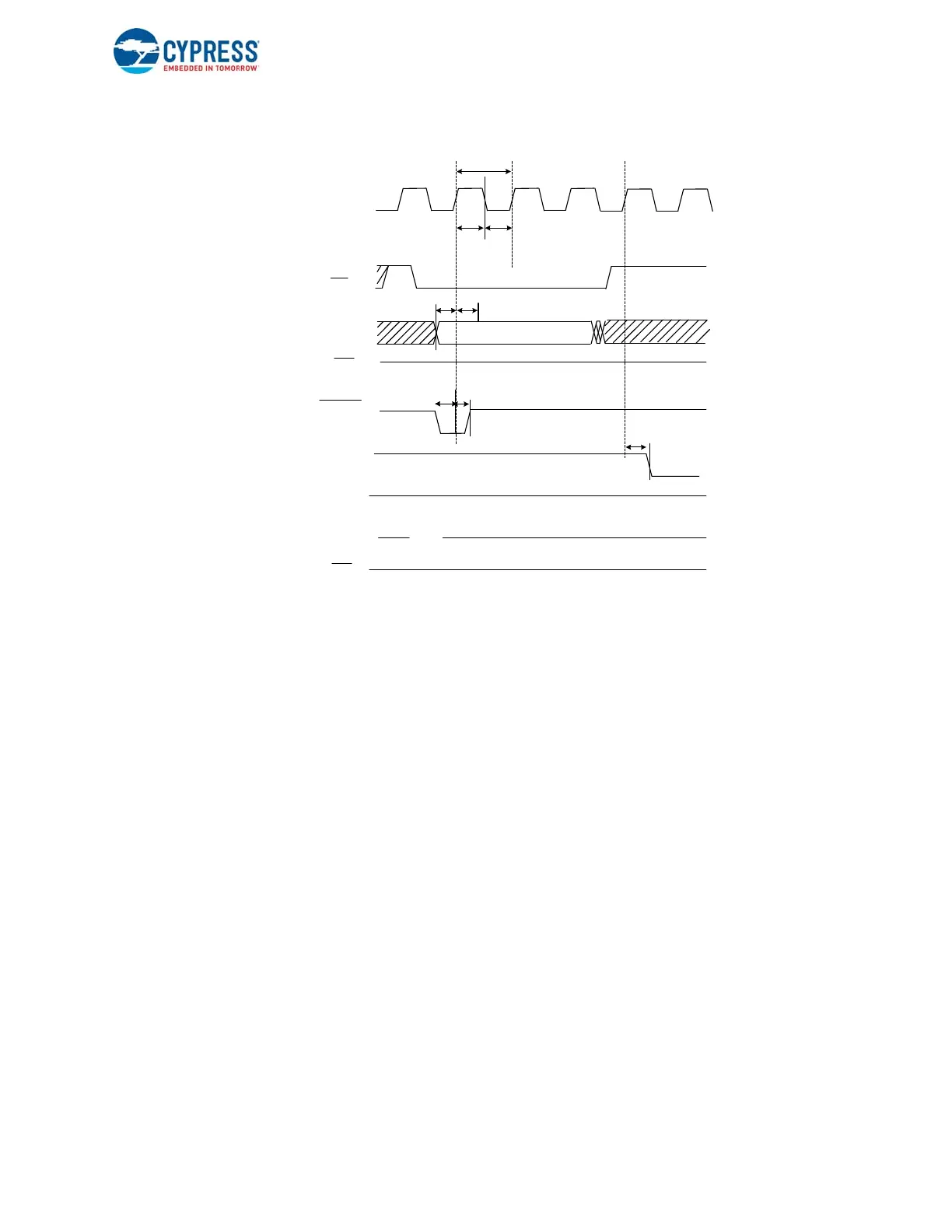
Figure 7-53. Synchronous ZLP Write Cycle Timing
7.16.2 Synchronous Slave FIFO Write Sequence Description
The sequence for performing writes to the synchronous Slave FIFO interface is as follows.
1. The FIFO address is stable, and the signal SLCS# is asserted.
2. The external master/peripheral outputs the data onto the data bus.
3. SLWR# is asserted.
4. While SLWR# is asserted, data is written to the FIFO, and on the rising edge of PCLK, the FIFO pointer is incremented.
5. The FIFO flag is updated after a delay of tCFLG from the rising edge of the clock.
The same sequence of events applies to a burst write.
Note: In the burst mode, SLWR# and SLCS# are left asserted for the entire duration of the burst write. In the burst write
mode, after SLWR# is asserted, the value on the data bus is written into the FIFO on every rising edge of PCLK. The FIFO
pointer is updated on each rising edge of PCLK.
Short Packet: A short packet can be committed to the USB host by using the PKTEND# signal. The external device/processor
should be designed to assert the PKTEND# along with the last word of data and the SLWR# pulse corresponding to the last
word. The FIFOADDR lines must be held constant during the PKTEND# assertion. On assertion of PKTEND# with SLWR#,
the GPIF II state machine interprets the packet to be a short packet and commits it to the USB interface. If the protocol does
not require any short packets to be transferred, the PKTEND# signal may be pulled high.
Note that in the read direction, there is no specific signal to indicate that a short packet has been sourced from USB. The
empty FLAG must be monitored by the external master to determine when all the data has been read.
Zero-Length Packet: The external device/processor can signal a ZLP by asserting PKTEND#, without asserting SLWR#.
SLCS# and the address must be driven as shown in Figure 7-53.
FLAG Usage: FLAG signals are monitored by the external processor for flow control. FLAG signals are FX3 outputs that may
be configured to show empty/full/partial status for a dedicated thread or the current thread being addressed.
PCLK
FIFO ADDR
t
CYC
t
CH
t
CL
t
AS
SLCS
SLWR
(HIGH)
Data IN
High-Z
PKTEND
SLOE
(HIGH)
An
t
AH
FLAGA
dedicated thread FLAG for An
(1 = Not Full 0= Full)
FLAGB
dedicated thread FLAG for Am
(1 = Not Full 0= Full)
t
PEH
t
PES
t
CFLG

 Loading...


