EZ-USB FX3 Technical Reference Manual, Document Number: 001-76074 Rev. *F 149
General Programmable Interface II (GPIF II)
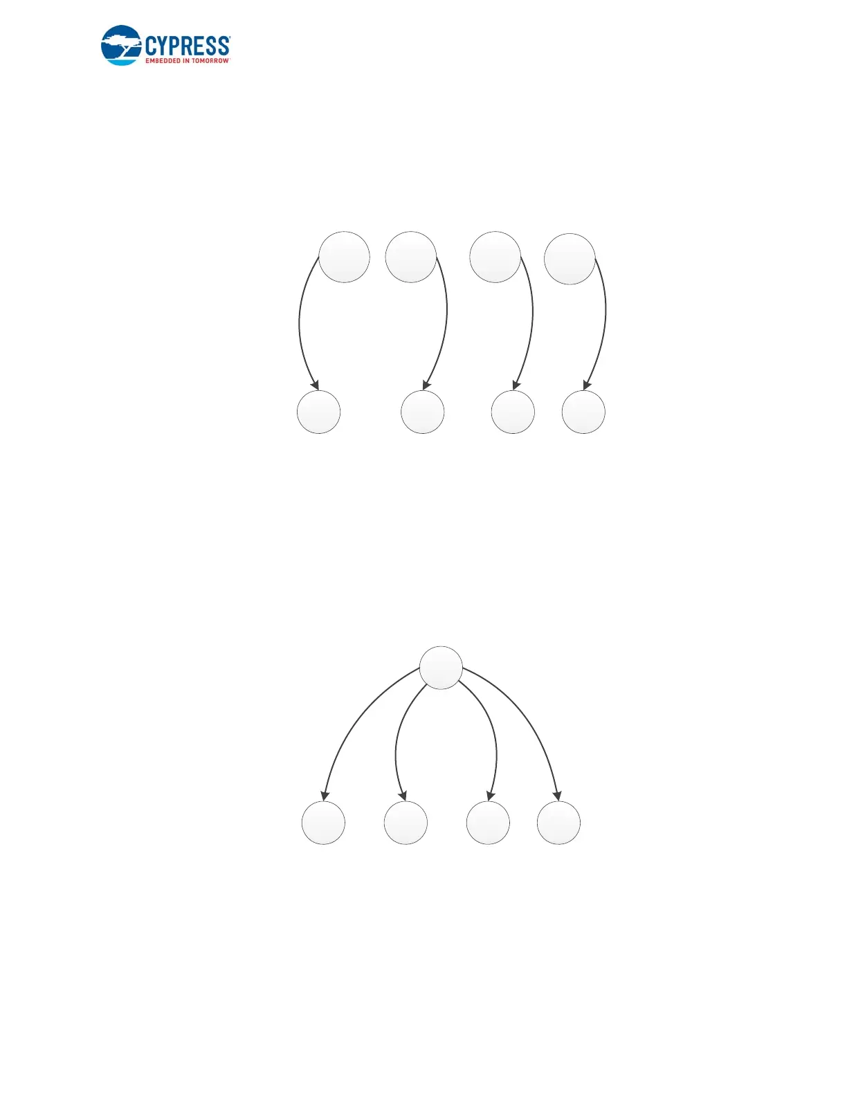
The GPIF II Designer tool converts this state machine fragment into the implementation shown in Figure 7-33, which has four
mirror state machines. The conditions under which each of the four mirrors is active are listed on top. All the transitions that
are shown going to the right share the same transition equation, and the actions specified in these states are nonconflicting.
Figure 7-33. Slave FIFO Interface Example Implementation with Mirror States
7.7.4 Guidelines for Transition Equation Entry
In some cases, GPIF II Designer is unable to reduce the input state machines to an implementable form because of
insufficient input information.
For example, consider another form of the state machine fragment shown in Mirror State Example on page 148. This version
of the state machine cannot be converted into multiple mirrored state machines that satisfy the mirroring rules using any
global trigger combination.
Figure 7-34. State Machine Example with Mirror States
The problem is that the transition equations are not fully defined. For example, the tool needs to assume that the IDLE RD
transition can happen independent of the values of the WR and END signals. If all the transition equations are made
completely defined by adding the expected values for the other input signals, the state machine is transformed into the
version shown in the example, and the tool can reduce the state machine to an implementable form.
IDLE_0
RD ZLP WR SLP
R
D
!
R
D
!
R
D
IN_ADDR
DR_DATA
COMMIT
IN_DATA
COMMIT
IN_DATA
COMMIT
IDLE_1 IDLE_2
IDLE_3
!
R
D
WR=0
END=0
WR=0
END=1
WR=1
END=0
WR=1
END=1
IDLE
RD WR SLP ZLP
R
D
W
R
&
!
E
N
D
W
R
&
E
N
D
!
W
R
&
E
N
D
IN_ADDR
DR_DATA
IN_DATA
IN_DATA
COMMIT
COMMIT

 Loading...


