EZ-USB FX3 Technical Reference Manual, Document Number: 001-76074 Rev. *F 434
HOST_RESP_CS
0xE003201C
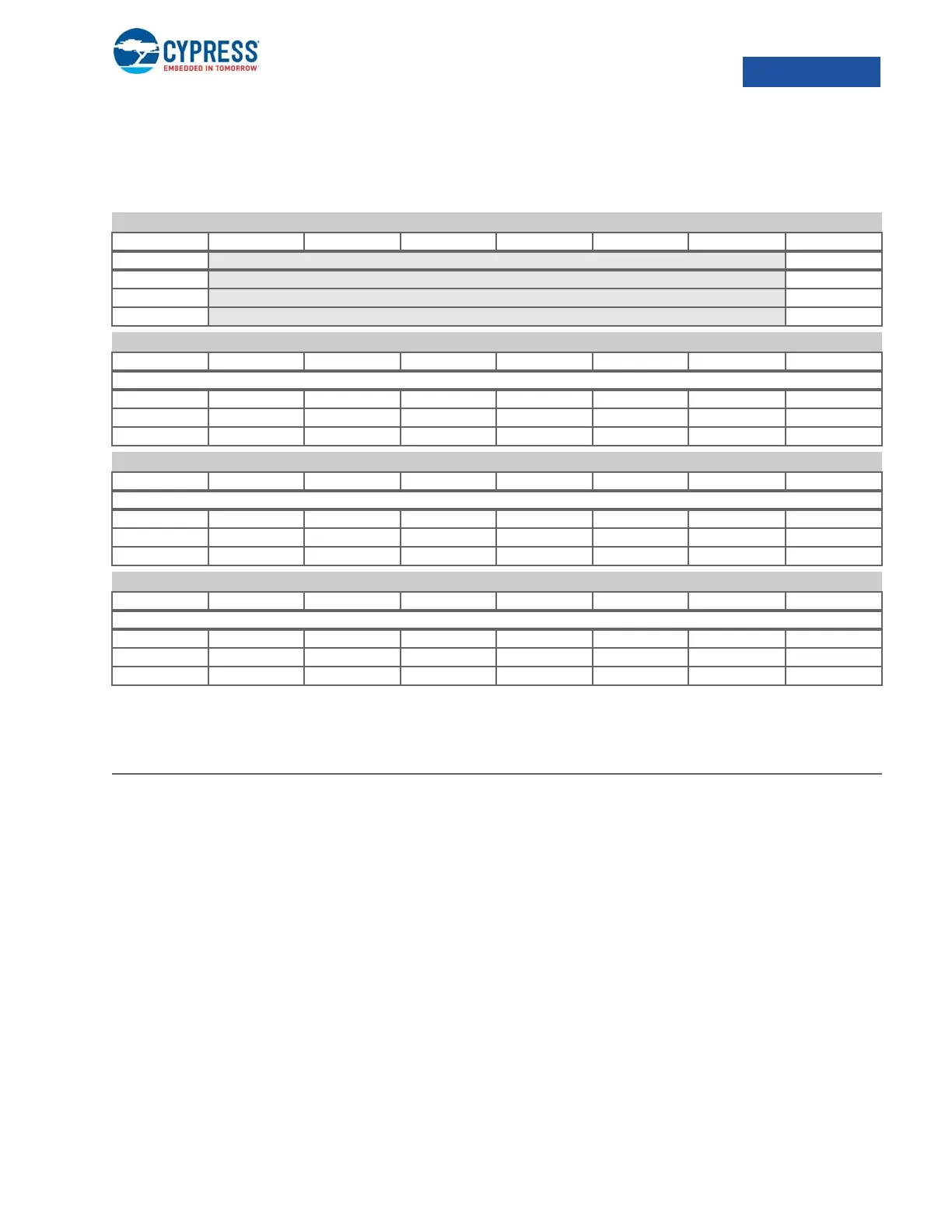
10.14.8 HOST_RESP_CS
Scheduler Response Command and Control Register
31 LIM_ERROR Hardware will set this bit as a scheduler response is written with WR_PTR = LIMIT (this indicates and
overflow in response memory). Software must clear this bit by writing 0 to it.
24 WR_RESP_COND This is a condition used counting the packet on USB bus. The packet counter is used for the
RESP_RATE specified in the scheduler memory.
0 The packet counter increments when the device does not NAK. The response from device
could be: ACK, STALL, NYET, PID_ERROR, Data toggle mismatch, CRC16_ERROR,
Time-Out.
1 The packet counter increments when the transaction is successful. The successful transac-
tion definition is:
IN-Token: No CRC16/PID/PHY Error, No toggle mismatch, No Babble,
No STALL, No NYET, No NAK, No Timeout
OUT-TOKEN: No CRC16/PID/PHY Error, No STALL, No NAK,
No NYET for PING token
23:16 WR_PTR Position at which next schedule response entry will be written (not itself a valid entry).
15:8 LIMIT Response entry which, when written, would constitute an overflow error.
7:0 MAX_ENTRY Maximum number of entries scheduler responses are written into memory. Responses are written in
order of completion, wrapping at end of buffer (see UIB_HOST_RESP_CS)
HOST_RESP_CS Scheduler Response Command and Control Register 0xE003201C
b31 b30 b29 b28 b27 b26 b25 b24
LIM_ERROR WR_RESP_COND
R/W0C R/W
R/W1S
R
0
0
HOST_RESP_CS Scheduler Response Command and Control Register
b23 b22 b21 b20 b19 b18 b17 b16
WR_PTR[7:0]
RRRRRRRR
R/W R/W R/W R/W R/W R/W R/W R/W
00000000
HOST_RESP_CS Scheduler Response Command and Control Register
b15 b14 b13 b12 b11 b10 b9 b8
LIMIT[7:0]
R/W R/W R/W R/W R/W R/W R/W R/W
RRRRRRRR
00000000
HOST_RESP_CS Scheduler Response Command and Control Register
b7 b6 b5 b4 b3 b2 b1 b0
MAX_ENTRY[7:0]
R/W R/W R/W R/W R/W R/W R/W R/W
RRRRRRRR
00000000
Bit Name Description

 Loading...


