EZ-USB FX3 Technical Reference Manual, Document Number: 001-76074 Rev. *F 171
Low Performance Peripherals (LPP)
1. Control Phase: This phase consists of the addresses being transmitted before the actual read or write data starts. It is
mainly handled by the I2C_PREAMBLE_CTRL and I2C_PREAMBLE_DATA registers. The I2C_PREAMBLE_DATA regis-
ter is 8 bytes long. Start and stop conditions after each byte (0: before first byte) are specified in the 16-bit I2C_PREAM-
BLE_CTRL register.
2. Data Phase: This phase is handled by the I2C_COMMAND and I2C_BYTE_COUNT registers. The data phase can be
connected to either DMA- or register-based data paths. DMA programming is the same as for other blocks and is not
explained here.
8.2.3.2 Register-Based I2C Transfers
The FX3 firmware uses the I2C_PREAMBLE_CTRL, I2C_PREAMBLE_DATA, and I2C_COMMAND registers to initiate an
operation. It then performs writes or reads from the TX and RX registers. ARM registers that transmit data from the ARM core
to an external interface (in this case, I2C) are called EGRESS_DATA registers. For the receive function, that is, when READ
is set in the I2C_COMMAND register, the data is received from the external interface (in this case, I2C) and pushed into the
registers, called INGRESS_DATA registers. The firmware can be notified of completion by interrupt or by polling through the
status register. A register I2C_BYTE_COUNT is used to specify the number of bytes to be written out and the same register is
also used to determine the number of bytes received.
4-byte-deep FIFOs hold egress and ingress data in its register space. Based on the status of these FIFOs, the TX_SPACE,
TX_HALF, TX_DONE and RX_DATA, RX_HALF flags are set in the I2C_STATUS and I2C_INTR registers.
The firmware can clear the FIFOs by asserting TX_CLEAR and RX_CLEAR from the I2C_CONFIG register. Table 8-1 shows
the conditions for the assertion of flags:
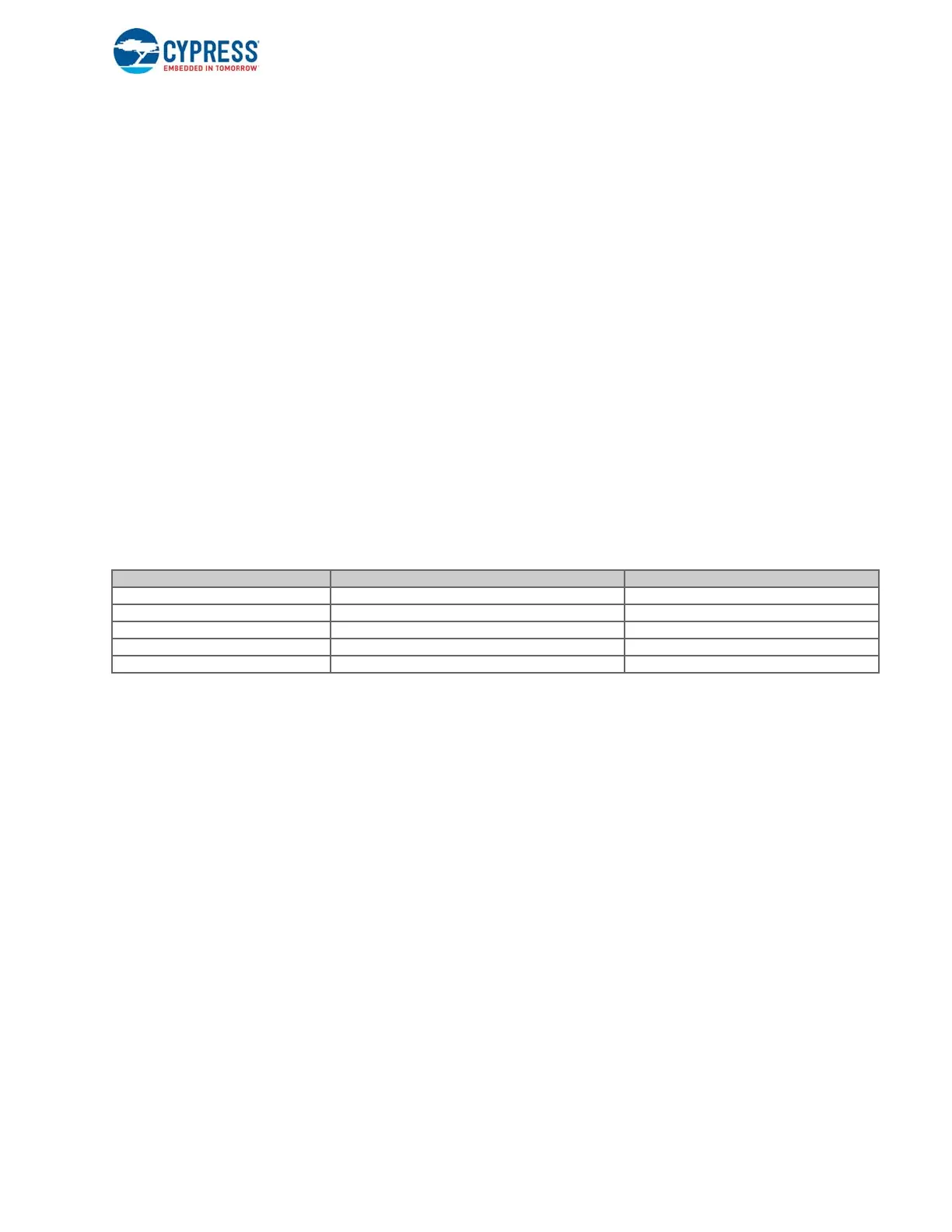
Table 8-1. Conditions for Assertion of Flags
8.2.3.3 DMA-Based I2C Transfers
DMA-based transfers use the I2C sockets. The DMA interface supports sockets that are used for moving the data between
the peripheral and the USB 3.0 interconnect. DMA sockets that transmit I2C data are called egress sockets, and DMA
sockets that receive I2C data are called ingress sockets. I2C data is pushed into the DMA socket, when I2C interface is
configured for READ in I2C_COMMAND register. The FX3 firmware uses the I2C_PREAMBLE_CTRL,
I2C_PREAMBLE_DATA, and I2C_COMMAND registers to initiate an operation. The I2C transceiver reads the preamble and
command and then initiates the operation after consulting the availability of ingress or egress sockets. Ingress and egress
sockets can be programmed to interrupt the CPU upon transaction completion. The I2C controller always raises interrupts in
error conditions.
Once the expected number of data bytes has been received (indicated by BYTE_COUNT), then an end of transfer is
indicated to the DMA adapter by setting the flag RX_DONE (of I2C_STATUS and I2C_INTR) in both the register- and DMA-
based transfers.
At any point, the status of the I2C block can be read from I2C_COMMAND.I2C_STAT bits to indicate the status of the block
and I2C lines.
8.2.3.4 Starting a Transaction
1. Select the DMA mode and enable the block through the I2C_CONFIG register. This step needs to be done only once after
booting, unless you want to change the data-path used in the data phase.
2. Program the I2C Byte count register to indicate the number of bytes to be transferred in the data phase. If you want the
data phase to continue without any limit on the number of bytes, then program 0xFFFFFFFF. In this case, the data phase
Flag Asserted Egress FIFO State Ingress FIFO State
TX_SPACE Not full -
TX_HALF At least half empty -
TX_DONE Full -
RX_DATA - Not empty
RX_HALF - At least half full

 Loading...


