EZ-USB FX3 Technical Reference Manual, Document Number: 001-76074 Rev. *F 150
General Programmable Interface II (GPIF II)
In general, specifying each transition equation (particularly for transitions originating from a state that has more than two
output transitions) fully by listing the expected value of all trigger inputs helps the tool find a mapping of the state machine to
the GPIF II hardware. In the absence of such data, the tool treats the unspecified triggers as don't cares for a particular
transition and may fail to find an implementable mapping.
It is also recommended to avoid transition equations that involve multiple OR clauses in states that have more than two output
transitions. This is because transition equations that have OR clauses typically cannot be refactored to remove global
triggers.
7.7.5 Intermediate States
If the design allows adding one or more clocks to a transition, intermediate states can be inserted into the state machine to
reduce the number of state transitions originating at a state.
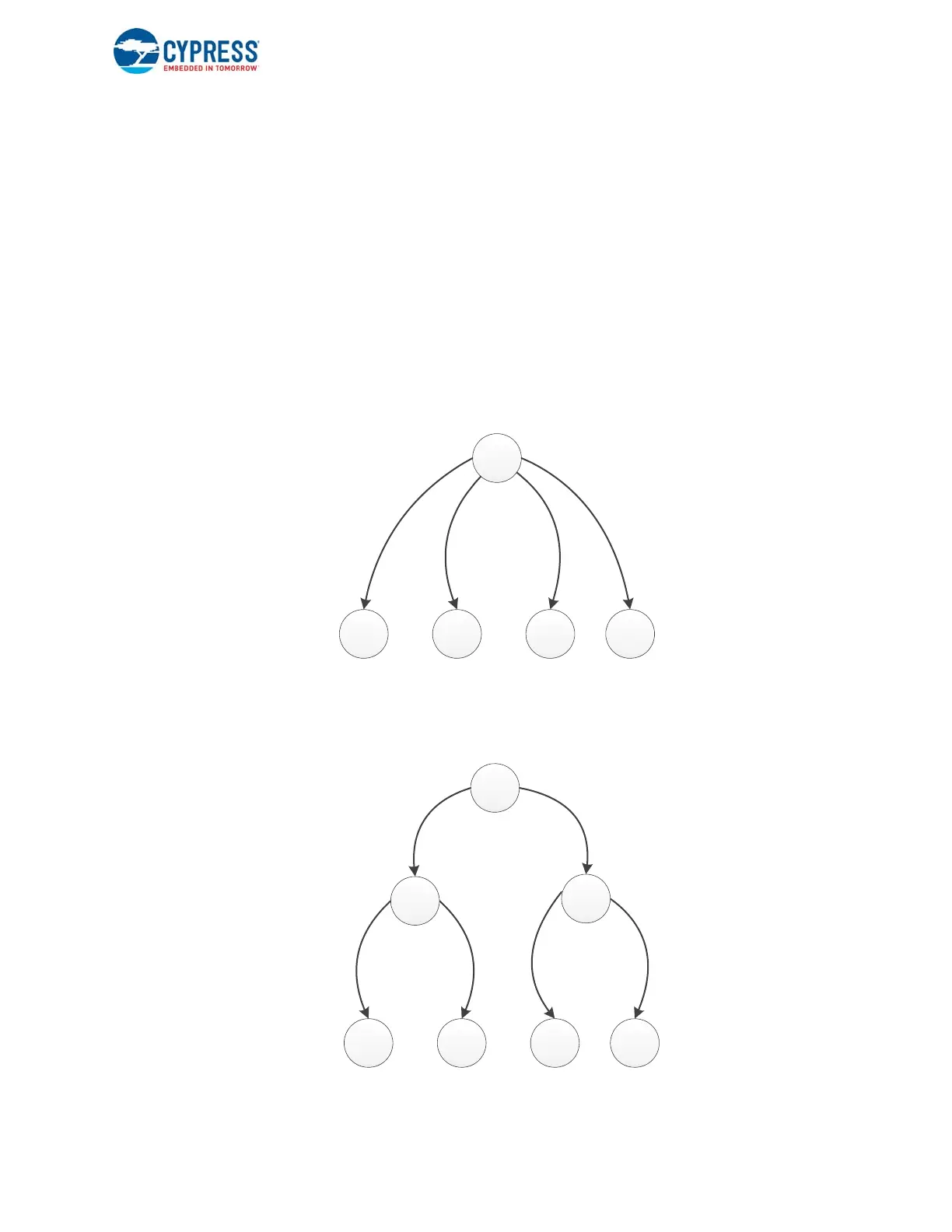
Consider the state machine fragment shown in Figure 7-35. There are four transitions originating at state S0, with the
transition equations F1, F2, F3, and F4 respectively.
Figure 7-35. Example State Machine with Multiple Transitions
This state machine can be transformed into the version shown in Figure 7-36. Here Sx and Sy are dummy states that have
been inserted to meet the constraint that each state can have only two outgoing transitions.
Figure 7-36. GPIF II Implementation for Multiple Transitions Avoiding Mirror States
S0
S1 S2 S3 S4
F
1
F
2
F
3
F
4
Sx
Sy
F
1
|
F
2
F
3
|
F
4
 Loading...


