EZ-USB FX3 Technical Reference Manual, Document Number: 001-76074 Rev. *F 85
Universal Serial Bus (USB)
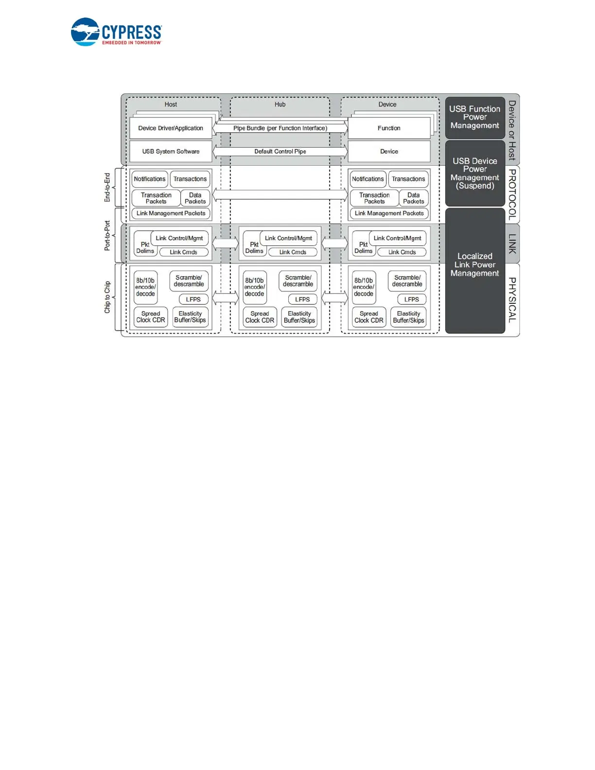
Figure 6-2. SuperSpeed (USB 3.0) Architecture
6.6.2 Physical Layer
The physical layer defines the PHY portion of the port and the physical connection between a downstream facing port (on a
host or hub) and an upstream facing port (on a device). The FX3 USB 3.0 function physical connection comprises two
differential data pairs, one transmit path and one receive path. The nominal signaling data rate is 5 Gbps. The electrical
aspects of each path are characterized as a transmitter, channel, and receiver; these collectively represent a unidirectional
differential link. Each differential link is AC-coupled with capacitors located on the transmitter side of the differential link. The
channel includes the electrical characteristics of the cables and connectors.
At an electrical level, each differential link is initialized by enabling its receiver termination. The transmitter is responsible for
detecting the far-end receiver termination as an indication of a bus connection and informing the link layer so the connect
status can be factored into link operation and management. When receiver termination is present but no signaling is occurring
on the differential link, it is considered to be in the electrical idle state. In this state, LFPS is used to signal initialization and
power management information. The LFPS is relatively simple to generate and detect and uses very little power.
FX3 USB 3.0 PHY has its own clock domain with Spread Spectrum Clock (SSC) modulation. The USB 3.0 cable does not
include a reference clock, so the clock domains on each end of the physical connection are not directly connected. Bit-level
timing synchronization relies on the local receiver aligning its bit recovery clock to the remote transmitter's clock by phase-
locking to the signal transitions in the received bit stream. The receiver needs enough transitions to reliably recover clock and
data from the bit stream. To assure that adequate transitions occur in the bit stream independent of the data content being
transmitted, the transmitter encodes data and control characters into symbols using an 8b/10b code. Control symbols are
used to achieve byte alignment and are used for framing data and managing the link. Special characteristics make control
symbols uniquely identifiable from data symbols.
The signal (timing, jitter tolerance, and so on) and electrical (DC characteristics, channel capacitance, and so on.)
performance of SuperSpeed links is defined with compliance requirements specified in terms of transmit and receive signaling
eye diagrams. The FX3 USB 3.0 function physical layer receives 8-bit data from the link layer and scrambles the data to
reduce EMI emissions. It then encodes the scrambled 8-bit data into 10-bit symbols for transmission over the physical
connection. The resultant data is sent at a rate that includes spread spectrum to further lower the EMI emissions. The bit
stream is recovered from the differential link by the receiver, assembled into 10-bit symbols, and decoded and descrambled,
producing 8-bit data that is then sent to the link layer for further processing.

 Loading...


