EZ-USB FX3 Technical Reference Manual, Document Number: 001-76074 Rev. *F 158
General Programmable Interface II (GPIF II)
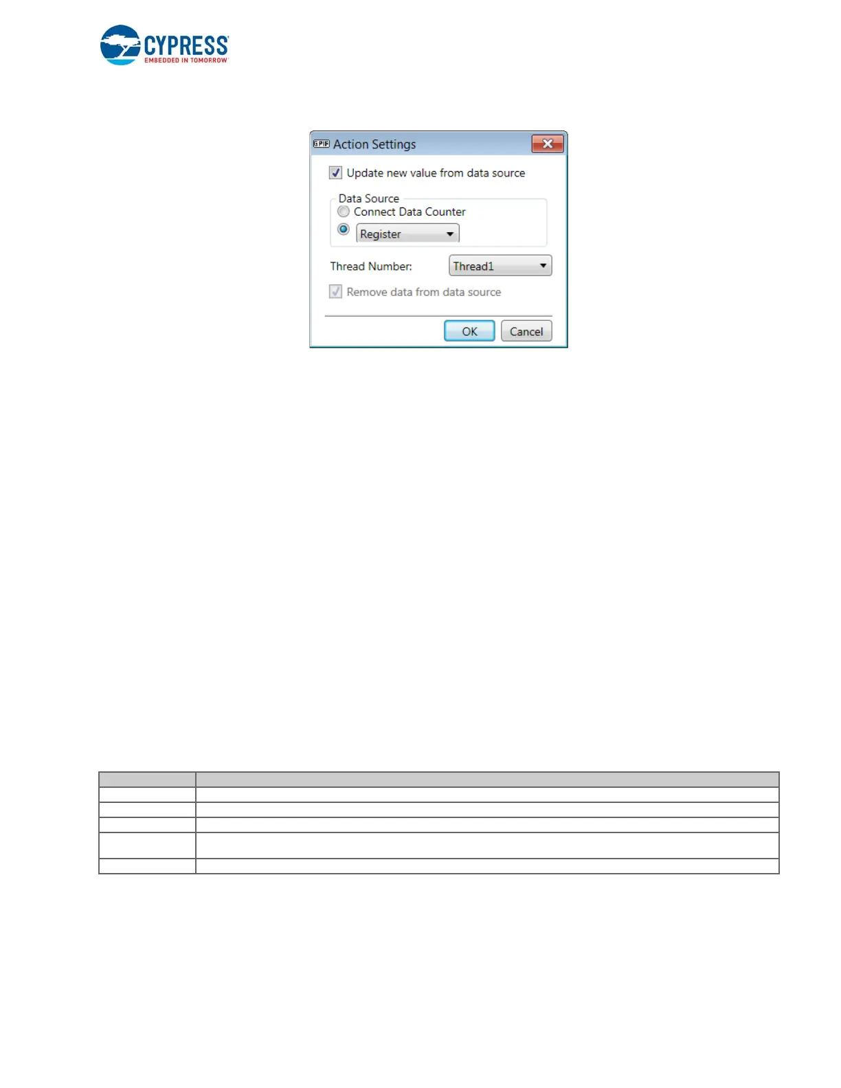
Figure 7-45. OUT_DATA Action Settings
Selecting the option Remove data from data source will clear the OUT_REGx_VALID field of the GPIF_DATA_CTRL register.
7.15 Implementing Synchronous Slave FIFO Interface
This section explains the steps involved in designing a Slave FIFO interface using the FX3 GPIF II block.
The first step is to configure the GPIF II outside-world interface by filling out the entries in the Interface Settings tab.
Selections applicable to the synchronous Slave FIFO interface are as follows.
■ Interface type: Slave
■ Communication type: Synchronous
■ Clock settings: External
■ Active clock edge: Positive
■ Endianness: Little endian
■ Data bus width: 8 Bit, 16 Bit, 24 Bit, or 32 Bit, as required
■ Address/data bus multiplexed: Deselected (nonmultiplexed)
■ Number of address pins used: 2 for selecting among the four threads available
■ Special functions: OE: This feature is available only with GPIO_19. With this function, the assertion of GPIO_19 can
directly change the data bus direction for the egress path (out of the FX3 device).
■ There are five input signals: SLCS#, SLWR#, SLRD#, SLOE#, and PKTEND#. All are active low signals.
Table 7-5. Slave FIFO Interface signal description
Four DMA flags (FLAGA, FLAGB, FLAGC, and FLAGD) are provided to the external peripheral to manage the data flow.
Figure 7-46 shows the FLAGA settings.
Signal Name Signal Description
SLCS# The chip select signal for the Slave FIFO interface. It must be asserted to perform any access to the Slave FIFO interface.
SLWR# The write strobe for the Slave FIFO interface. It must be asserted to perform write transfers to the Slave FIFO.
SLRD# The read strobe for the Slave FIFO interface. It must be asserted to perform read transfers from the Slave FIFO.
SLOE#
The output enable signal. It causes the data bus of the Slave FIFO interface to be driven by FX3. It must be asserted to perform read
transfers from the Slave FIFO.
PKTEND# The packet end signal. It must be asserted to send a short packet to the USB host.

 Loading...


