EZ-USB FX3 Technical Reference Manual, Document Number: 001-76074 Rev. *F 136
General Programmable Interface II (GPIF II)
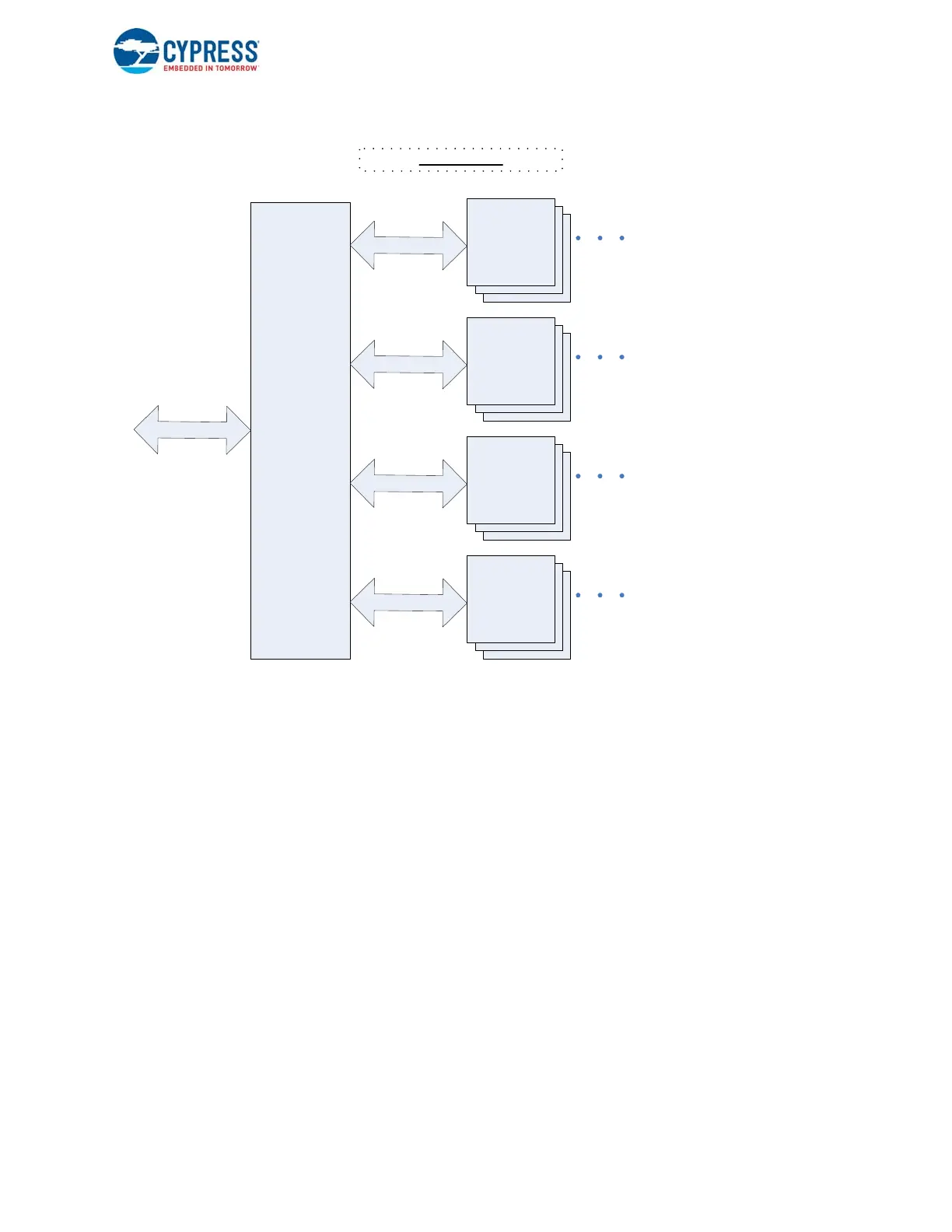
Figure 7-18. GPIF II - PP_MODE=0
The second mode is PP_MODE=1. In this mode, while the four independent threads still exist, only one thread (Thread0) is
used, through which all sockets are accessed. In this mode, the external processor must first write to a few FX3 registers over
the GPIF II interface. These registers have 8-bit addresses; hence, in PP_MODE=1, having at least an 8-bit-wide address
bus on the interface is a requirement. By writing certain FX3 registers (PP_DMA_XFER and PP_DMA_SIZE), the socket
number and amount of data to be transferred are specified. Then when data access begins, the data is automatically routed
through thread 0, to and from whichever socket number was specified earlier in the register, as shown in Figure 7-19.
GPIFII
up to 8 sockets can be mapped to each thread
T
h
r
e
a
d
0
Socket with
associated
buffers
allocated
up to 8 sockets can be mapped to each thread
T
h
r
e
a
d
1
Socket with
associated
buffers
allocated
up to 8 sockets can be mapped to each thread
T
h
r
e
a
d
3
Socket with
associated
buffers
allocated
up to 8 sockets can be mapped to each thread
T
h
r
e
a
d
2
Socket with
associated
buffers
allocated
A
d
d
r
e
s
s
b
u
s
PP_MODE = 0

 Loading...


