EZ-USB FX3 Technical Reference Manual, Document Number: 001-76074 Rev. *F 198
Storage Ports
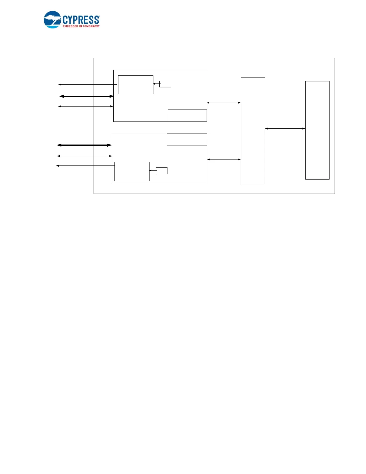
Figure 9-1. SIB Block Diagram
SIB consists of three major subblocks.
■ S0 core
■ S1 core
■ DMA adapter
The S0 and S1 core are functionally independent, thus can be configured independently. This also allows to clock gate one of
the cores based on the active port. All protocol-related translation and error handling is done by the respective cores. The
cores provide a simple request/data interface to the DMA backbone.
The S0/S1 core contains a CLOCK CONTROL sub-block. The clock control block accepts the core clock as the input and
generates the clocks required for the SIB. This block instantiates the Delay-Locked Loop (DLL) and performs the following
functions:
■ Gating of clock when sockets cannot accept data
■ Gating of clock when sockets do not have data
■ Gating of clock when data transfer of all blocks has been completed
■ Gating of DLL master clock when the block is IDLE
■ Gating of clock only on block boundaries
■ Generating pin sample clocks and core clocks used by the core
■ Keeping track of when DLL locks and loses lock
Each DLL is used to:
■ Internally generate 16 equally spaced phases of input signal. This allows clock control in 22.5º increments. A phase picker
circuit at the DLL output stage picks up to a maximum of 4 of these 16 output phases to guarantee no setup and hold time
issues on-chip. The input reference frequency range of the signal input clock is 25-208 MHz. This is utilized for SD3.0
Host Tuning Feature, discussed in SD3.0 Host Tuning Feature on page 223.
The DMA adapter is used to interface to the DMA interconnect of the FX3S device. All DMA data through the interface is
assembled at the core and then forwarded to the DMA adapter to transfer over the system interconnect. The channel to
access the DMA adapter is the thread. A thread controller converts the simple request-data interface from the core to the
required transactions on the DMA adapter. The DMA data enters the DMA adapter through two distinct pipes, named Thread
S0Core
DMAAdapter
THREAD_0
InterfacePins
Read/Writeaccess
toSIBsockets
S0Registers
SIBSockets[0–7]
SIBBlock
S1Core
S0_DAT[7:0]
S0_CMD
S0_CLK
S1_DAT[7:0]
S1_CMD
S1_CLK
S1Registers
SIBCLOCK
CONTROL
GCTL
THREAD_1
SIBCLOCK
CONTROL
GCTL

 Loading...


