A
B
C
D
E
F
G
H
L
M
N
P
Mototelaio
Frame
sezione / section
H 2
14 ST3 - M.Y. 2004 - edizione/edition 00
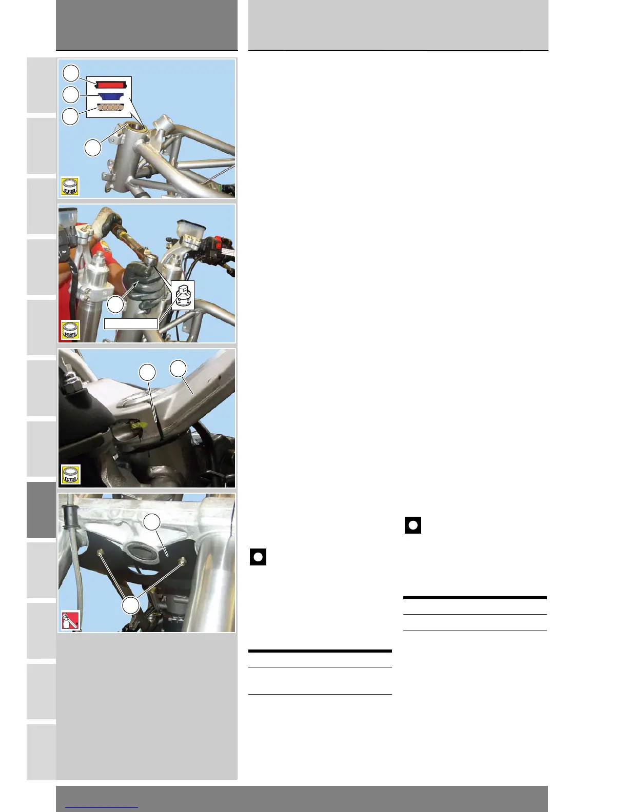
Inserire il perno di sterzo all’interno
del cannotto portandolo assialmente
in appoggio.
Installare il gruppo base di sterzo (9)
sul telaio.
Inserire sull'anello esterno superiore
(E) del telaio, la corona di sfere (B) op-
portunamente ingrassata.
Montare sul perno di sterzo l’anello in-
terno (A) del cuscinetto superiore (5),
con la parte di diametro maggiore, ri-
volta verso l'alto.
Montare l'anello di tenuta (4) con la
superficie piana verso l'alto.
Applicare grasso sulla ghiera (3) ed av-
vitare manualmente la ghiera (3) di
registro fino a portarla in battuta
sull’anello di tenuta (4).
Posizionare sulla ghiera (3) la bussola
speciale cod. 88713.1058 sulla quale
applicare la chiave dinamometrica.
Serrare la ghiera di registro (3) alla
coppia prescritta (Sez. C 3).
Rimontare i supporti semimanubri
come descritto alla (Sez. H 1).
Installare la testa di sterzo (2) sulla gh-
iera (3) facendo corrispondere le sedi
degli steli forcella con le corrispond-
enti sulla base di sterzo e i pioli della
testa di sterzo con i semimanubri vedi
capitolo “Rimontaggio supporto sem-
imanubri”di questa sezione.
Riposizionare gli steli forcella nel
modo descritto alla Sez. G 2.
Ingrassare la vite (1).
Bloccare la vite (1) sulla testa di sterzo
(2) alla coppia prescritta (Sez. C 3).
Se è stato rimosso il paraspruzzi (13)
applicare frenafiletti alle viti (10) e ser-
rare le viti alla coppia prescritta (Sez.
C 3).
Importante
Dopo aver rimontato la base di
sterzo è consigliabile eseguire la veri-
fica della sterzata come indicato alla
Sez. H 1.
Fissare il tubo freno anteriore alla
base di sterzo con la staffa di suppor-
to.
Operazioni Rif. Sez.
Rimontare la ruota
anteriore
G 1
Rimontare specchietti,
cupolino e plance
E 1
Push the steering shaft all the way
into the steering tube.
Fit the bottom yoke assembly (9) on
the frame.
Grease the ball ring (B) and fit it on
frame top outer ring (E).
Fit the upper bearing (5) inner ring (A)
with the larger diameter facing up to
steering shaft.
Install the oil seal (4) with the flat side
facing up.
Apply grease to the ring nut (3) and
manually tighten it into contact with
the seal ring (4).
Fit special bush part no. 88713.1058
to ring nut (3) and fit torque wrench to
bush.
Tighten adjusting ring nut (3) to the
specified torque (Sect. C 3).
Refit the handlebar mountings as
instructed above (Section H 1).
Fit the top yoke (2) over the ring nut
(3), carefully aligning the fork leg
holes with those in the bottom yoke
and the top yoke alignment pins with
the handlebar mountings. See
"Refitting the handlebar mountings" in
this chapter.
Fit the fork legs as instructed in
Section G 2.
Grease the pinch bolt (1).
Tighten the pinch bolt (1) on the top
yoke (2) to the specified torque
(Section C 3).
If you have removed the splash guard
(13), apply threadlock to the screws
(10) before tightening them to the
specified torque (Section C 3).
Caution
Once bottom yoke has been
assembled, check for steering proper
adjustment as described in Sect. D 4.
Secure front brake line to bottom
yoke with mounting bracket.
Operations See Sect.
Refit the front wheel G 1
Refit the rear view
mirrors, headlight
fairing and dash panels
H 1
A
4
A
B
4
B
88713.1058
3
B
2
1
2
LOCK
10
13