Repairs/Adjustments 08/20/2015 GBC AdvancedPunch Pro
4-14
REP 1.13 Interlock Switch Replacement
PARTS LIST ON PL 2.2
Use this procedure to remove and install the Interlock Switch Assembly.
Removal Procedure
WARNING
Do not perform repair activities with the power on or electrical power
supplied to the machine. Some machine components contain
dangerous electrical voltages that can result in electrical shock and
possible serious injury. See Section 0, page vi for other languages.
1. Switch power OFF to entire printing system.
2. Disconnect the Power Cord.
3. Open the Front Door.
4. Remove the M4 Nuts (2).
5. Remove the Interlock Switch Bracket.
Do not knock the Nuts (2) into the machine.
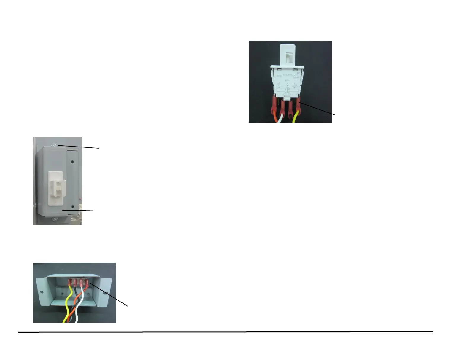
6. Press in the Tabs (2) on the sides of the Switch and remove the
Interlock Switch from the Interlock Switch Bracket.
7. Note the location of the Wires (4); then disconnect the Wires from the
Interlock Switch (PL 2.2).
From right to left:
Yellow wire – Position 8.
Black wire – Position 4.
White wire – Position 3.
Orange wire – Position 7.
8. Place the new Interlock Switch into the Interlock Switch Bracket. and
press down until the Tabs lock in place.
9. Connect the Wires (4) to the new Interlock Switch.
10. Place the interlock Switch Bracket in position, and tighten the Nuts
(2).
11. Close the Front Door.
12. Connect the Power Cord.
13. Power ON the entire printing system.