Repairs/Adjustments 08/20/2015 GBC AdvancedPunch Pro
4-126
ADJ 1.3 Die Stop Magnet Adjustment
If the ALIGNMENT MODE Procedure (GP 6.1) does not move the
inboard/outboard position of the punch holes far enough, use this
procedure to adjust the Die Stop Magnet to move the holes
inboard/outboard,
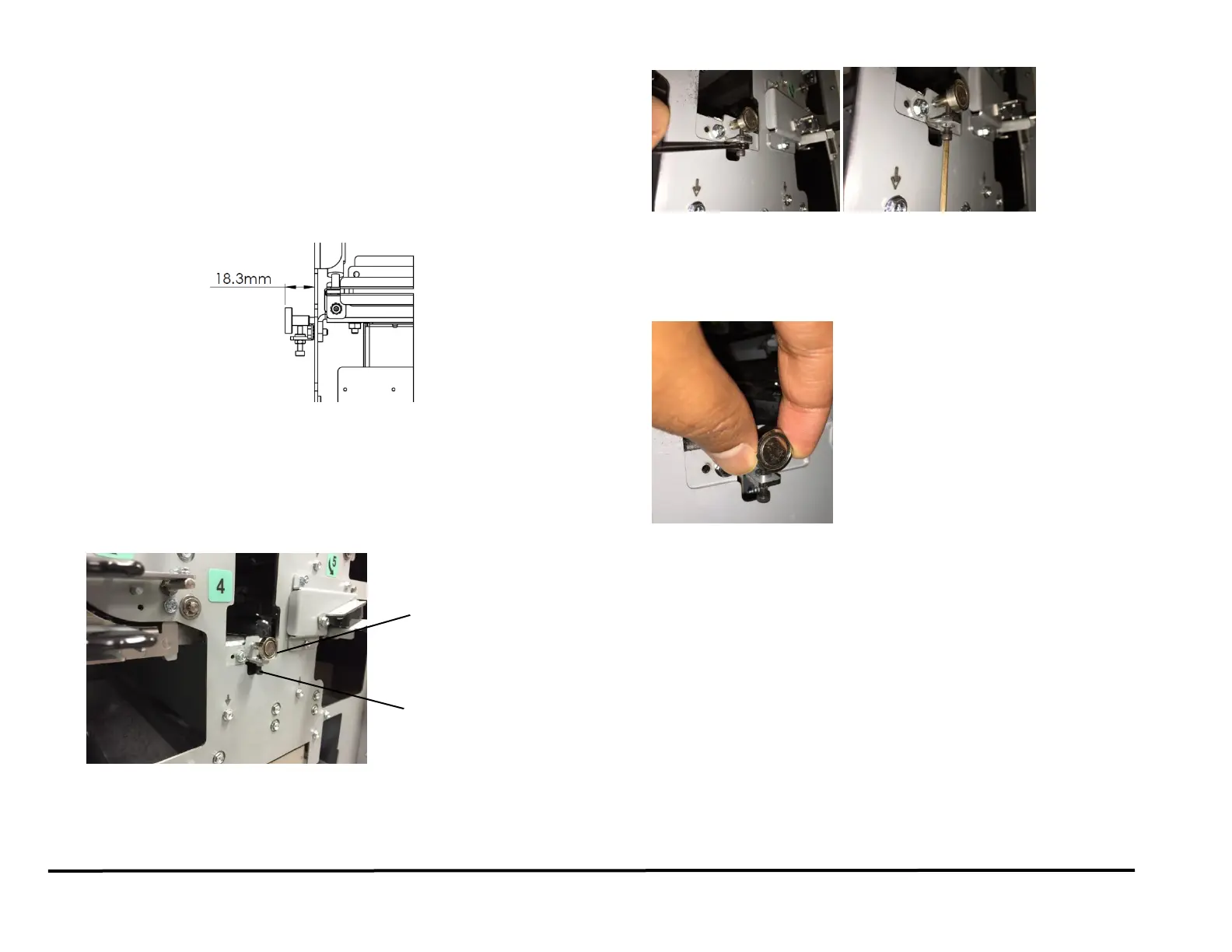
Note: The nominal position of the Die stop magnet face is 18.3mm from
the face of the Punch module frame
WARNING
Do not perform repair activities with the power on or electrical power
supplied to the machine. Some machine components contain
dangerous electrical voltages that can result in electrical shock and
possible serious injury. See Section 0, page vi for other languages.
1. Open the Front Door.
2. Remove the Die Set (see Operator Manual).
3. Loosen the Nut and Lock Screw.
4. Rotate the Die Set Magnet to adjust the position of the Die Set Stop.
Rotate the Die Set Magnet clockwise to move the hole toward the
rear of the Punch.
Rotate the Die Set Magnet counterclockwise to move the hole
toward the front of the Punch.
5. Tighten the Nut and Lock Screw.
6. Run some sheets of paper through the Punch Cycle.
7. Check the Alignment of the holes.
8. If necessary, repeat steps 3-6 until the alignment is centered (iterative
process).
9. Install the Die Set (see Operator Manual).
10. Close the front Door.



 To Next Page