Repairs/Adjustments 08/20/2015 GBC AdvancedPunch Pro
4-64
REP 2.24 Bypass Open Sensor Replacement
PARTS LIST ON PL 3.7
Use this procedure to remove and install the Bypass Open Sensor (S27).
WARNING
Do not perform repair activities with the power on or electrical power
supplied to the machine. Some machine components contain
dangerous electrical voltages that can result in electrical shock and
possible serious injury. See Section 0, page vi for other languages.
1. Switch power OFF to entire printing system.
2. Disconnect the Power Cord.
3. Do GP 6.4 to undock the Punch from the upstream and downstream
equipment.
4. Do REP 1.11 Downstream side frame cover to remove the upper
cover.
5. Do REP 1.6 to remove the Rear Cover.
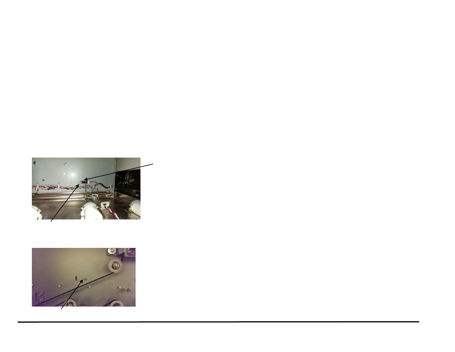
6. Disconnect the Sensor Connector at the Sensor.
7. Remove the Screw and Nut that secure the Sensor to the sheet metal
part.
Installation Procedure
1. Place the Sensor in position, then install and tighten the Screw and
the Nut.
2. Connect the Sensor Connector.
3. Do REP 1.6 to install the Rear Cover.
4. Do REP 1.11 Downstream side frame cover to install the upper cover.
5. Do GP 6.3 to dock the Punch to the upstream and downstream
equipment.
6. Connect the Power Cord.
7. Power ON the entire printing system.