GBC AdvancedPunch Pro 08/20/2015 Repairs/Adjustments
4-137
ADJ 1.7 Idler Panel Magnetic Latches Adjustment
Two round spacer studs should contact the drive panels completely (GP
6.16). When the Idler assembly is latched there should not be any
movement in the assembly. If there is movement/play, do the below steps
to adjust the assembly.
ADJ 1.7.1 Idler Panel Latches Adjustment procedure
This procedure applies to
Entrance Idler Panel (PL 4.2)
Exit Idler Panel (PL 4.4)
Upper Bypass Panel (PL 4.5)
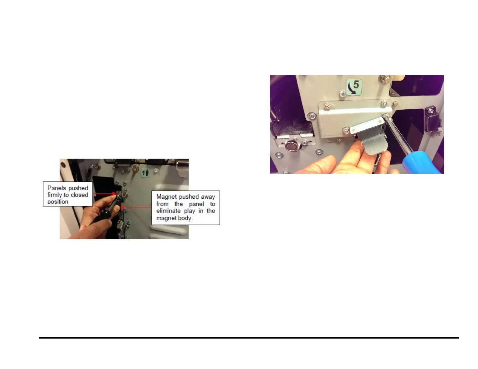
1. Loosen the two screws that hold the magnet. With the panel closed
firmly, pull away the magnet away from the drive panel (to eliminate
the play in the magnet) and tighten both screws. The screws should
be tightened while the panel is closed firmly and the magnet pulled
away as shown.
ADJ 1.7.2 Lower Exit panel latch Adjustment procedure
This procedure applies to
Lower Exit Panel Assembly (PL 3.1)
1. Loosen the two screws the hold the magnet. With the panel fully
closed (the panel will hit limiting tabs and you will hear a sound),
tighten the two screws.