Repairs/Adjustments 08/20/2015 GBC AdvancedPunch Pro
4-112
REP 3.15 Die Rail Assembly and Die Rail Springs Replacement
PARTS LIST ON PL 5.7
Removal Procedure
Use this procedure to remove and install the Die Rail Assembly and Die
Rail Springs
WARNING
Do not perform repair activities with the power on or electrical power
supplied to the machine. Some machine components contain
dangerous electrical voltages that can result in electrical shock and
possible serious injury. See Section 0, page vi for other languages.
1. Switch power OFF to entire printing system.
2. Remove the Die Set (see Operator Manual).
3. Disconnect the Power Cord.
4. Do REP 1.6 to remove the Rear Cover.
5. Do REP 3.1 to remove the Punch Module.
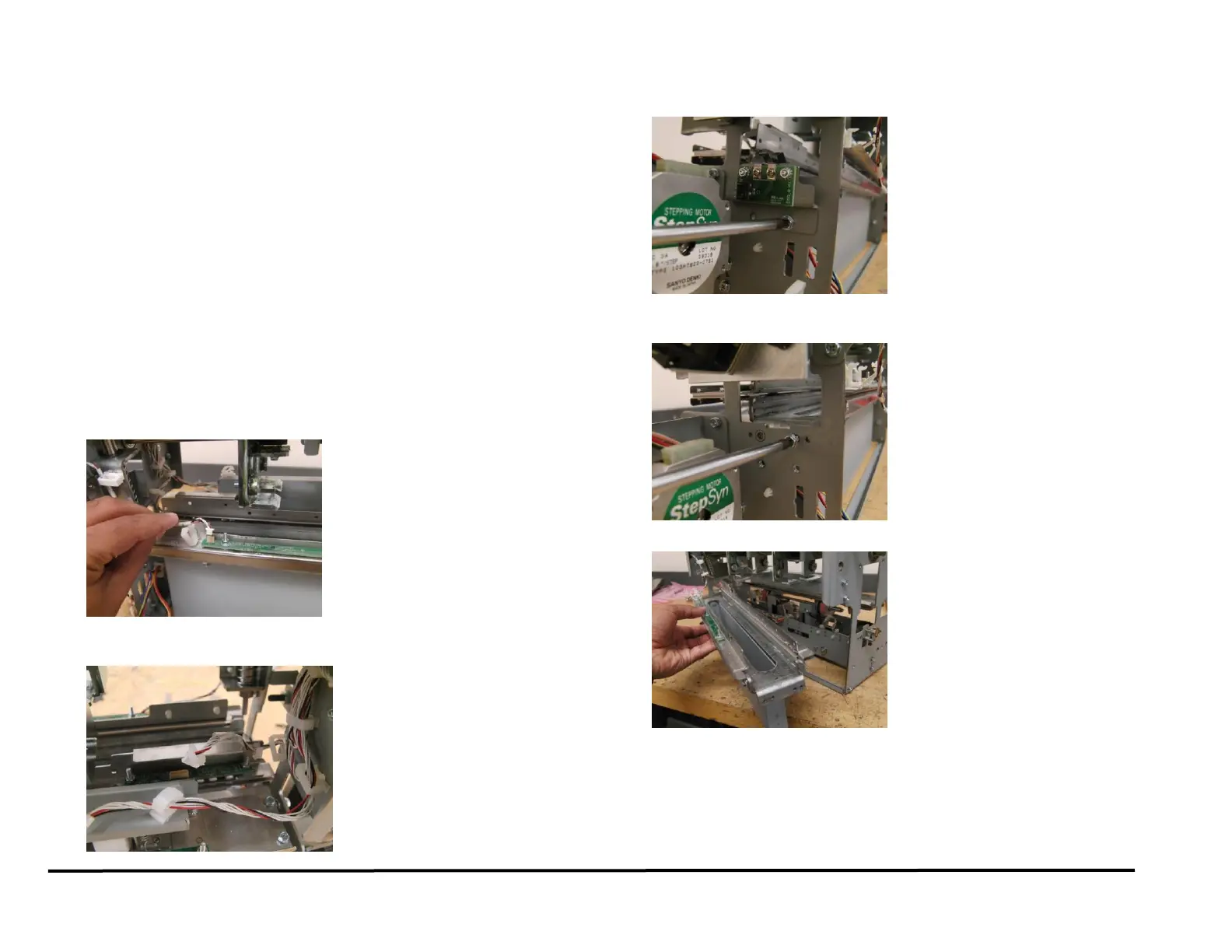
6. Unplug Back Gage Sensor Board and release the wires from cable
clamps.
7. Unplug Alignment Sensor Board and release the wires from the Cable
Clamps.
8. Remove the Screws (2) that hold the Dieset Recognition Bracket.
9. Remove the Screws (4) that hold that Die Rail Assembly- (2) from the
front and (2) from the rear.
10. Remove the Die Rail Assembly.