GBC AdvancedPunch Pro 08/20/2015 Repairs/Adjustments
4-23
REP 1.20 Drive roller Cover removal.
Use this Procedure to remove the Drive roller cover from entrance and
exit sides.
Removal Procedure
WARNING
Do not perform repair activities with the power on or electrical power
supplied to the machine. Some machine components contain
dangerous electrical voltages that can result in electrical shock and
possible serious injury. See Section 0, page vi for other languages.
1. Switch power OFF to entire printing system.
2. Disconnect the Power Cord.
3. Do REP 1.6 to remove the Rear Cover.
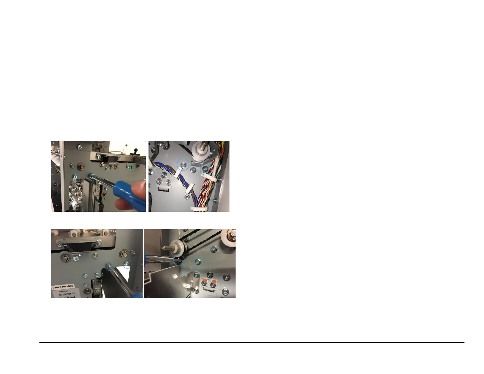
4. For Entrance side- Remove (2) screws from the front frame and (2)
screws from the rear frame.
5. For exit side- Remove (2) screws from the front frame and (2) screws
from the rear frame.
6. Remove the Drive roller cover.