GBC AdvancedPunch Pro 08/20/2015 Repairs/Adjustments
4-87
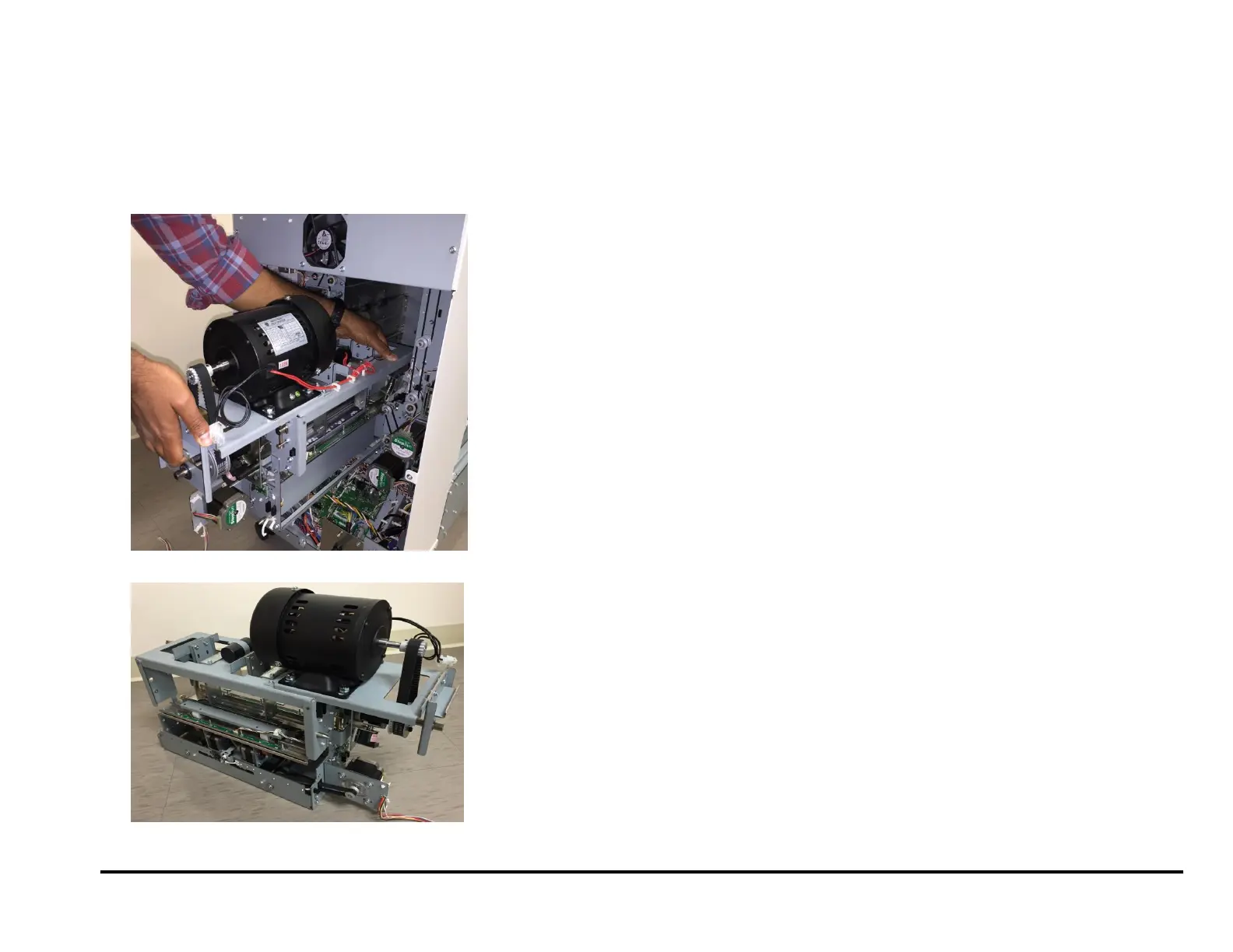
19. Do the following to remove the Punch Module
Grasp the handle near with one hand and pull to slide out the
Punch Module.
Support the Punch Module with your other hand as you slide it
out.
Make sure the punch module does not drop on the Control board
as you remove it.
Place the Punch Module on a flat surface.
REP 3.1.2 Punch Module Installation
Use this procedure to install the Punch Module.
1. Do the following to slide the Punch Module into the slot at the rear of
the machine.
Grasp the Clutch Pulley Sub Assembly with your right hand and
support the Punch Module with your left hand
Slide the Punch Module into the slot.
2. Do the following to install the Lock Plates (green).
Place the Lock Plates (2) in position).
Use a Phillips Head Screwdriver to tighten the Screws (2) through
the Lock Plates (2).
3. Connect all electrical Connectors (11).
Connector for Punch Motor M10.
Connector for Sensors S16 and S17.
Die Set Recognition Connector
Connectors (2) for the M3 Header and the M4 Header.
Connector for the M5 Motor Driver
Connector Solenoid SOL2.
Connector for Sensor S28.
Connectors (2) for Sensors S6-S10 and S11-S15.
4. Go to the front of the Punch
5. Tighten the M4 Screws (5) into the Front Frame.
6. Install the Die Lock Handle and tighten the M4 X 10 Phillips Head
Screw.
7. Install the Die Set (see Operation Instructions Manual).
8. Use the handle to lock the Die Set.
(Cont.)
9. Close the Front Door.
10. Do REP 1.6 to install the Rear Cover.
11. Connect the Power Cord.
12. Power ON the entire printing system.