Repairs/Adjustments 08/20/2015 GBC AdvancedPunch Pro
4-104
REP 3.10 Steering Idler Panel Weldment Replacement
PARTS LIST ON PL 5.4
Use this procedure to remove and install a Steering Idler Panel
Weldment.
Removal Procedure
WARNING
Do not perform repair activities with the power on or electrical power
supplied to the machine. Some machine components contain
dangerous electrical voltages that can result in electrical shock and
possible serious injury. See Section 0, page vi for other languages.
1. Switch power OFF to entire printing system.
2. Disconnect the Power Cord.
3. Do REP 1.6 to remove the Rear Cover.
4. Do REP 3.1 to remove the Punch Module.
5. Unplug the Skew Senor and release the Cable Clamp.
6. Remove the Screws (4) that hold the Steering Idler Panel Sub
Assembly to the Drive Panel Steering Sub Assembly.
7. Remove the Steering Idler Panel Sub Assembly.
8. Transfer the Skew Sensor, Steering Islder Roller, Idler roller Cover,
and all fasteners to the new Weldment.
Installation Procedure
1. Make sure the Spacers (2) are in position on the Steering Drive Panel
Weldment (use semi perfs for placement).
2. Place the Steering Idler Panel Sub Assembly in position on the Drive
Panel Steering Sub Assembly.
3. Install the Screws (4).
4. Do REP 3.1 to install the Punch Module.
5. Do REP 1.6 to install the Rear Cover.
6. Connect the Power Cord.
7. Power ON the entire printing system.
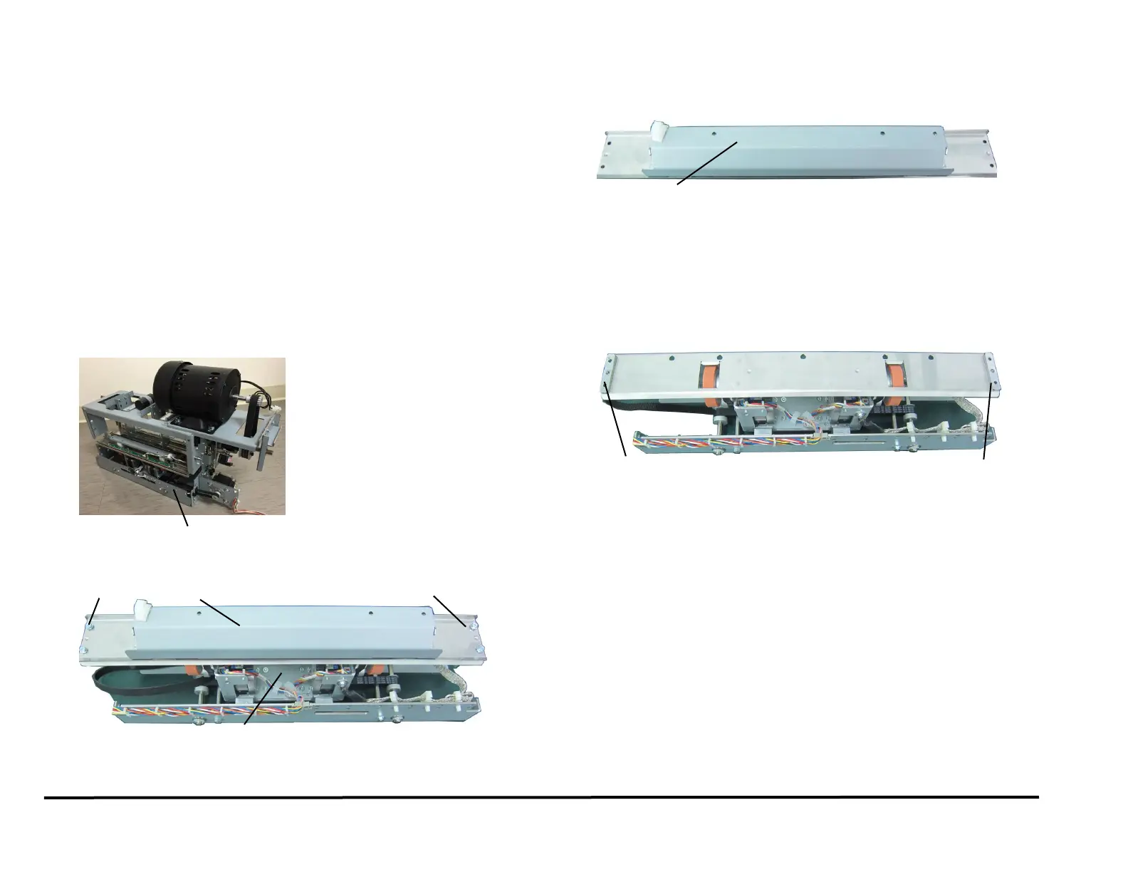
Steering Idler Panel Sub Assembly
Drive Panel Steering Sub Assembly
Steering Idler Panel Sub Assembly