Repairs/Adjustments 08/20/2015 GBC AdvancedPunch Pro
4-84
3. Punch Module
REP 3.1 Punch Module Replacement
PARTS LIST ON PL 5.1
Use this procedure to remove and install the Punch Module.
REP 3.1.1 Punch Module Removal
WARNING
Do not perform repair activities with the power on or electrical power
supplied to the machine. Some machine components contain
dangerous electrical voltages that can result in electrical shock and
possible serious injury. See Section 0, page vi for other languages.
1. Switch power OFF to entire printing system.
2. Disconnect the Power Cord.
3. Do REP 1.6 to remove the Rear Cover.
4. Open the Front Door.
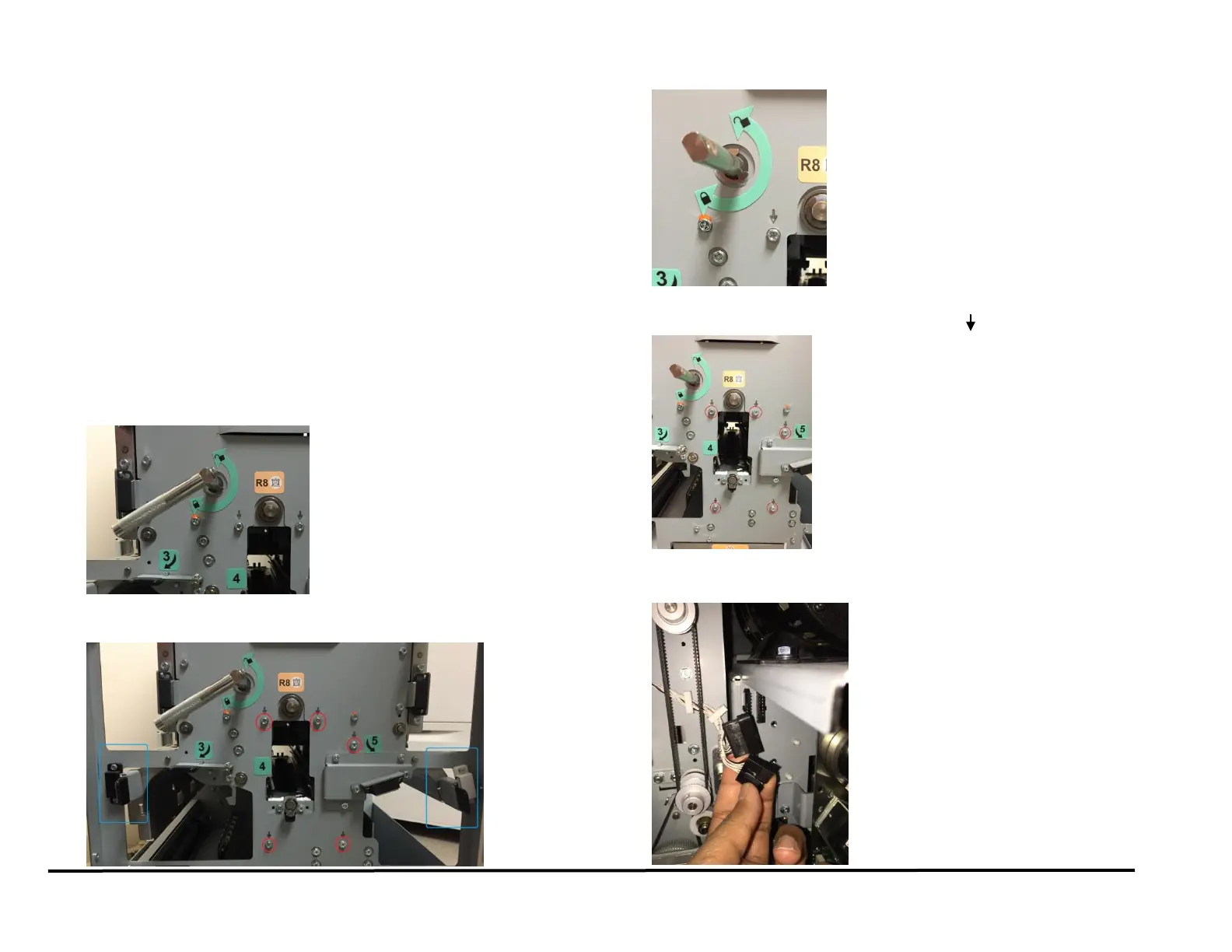
5. Use the handle to unlock the Die Set. Remove the Die set and insert
it into one of the Die storage racks.
6. Use the levers (blue) to open the Acceleration Roller Idler Panel and
the Accel Idler Panel compartments.
7. Remove the M4 X 10 Phillips Head Screw and the Die Lock Handle.
8. Remove the M4 Screws (5) from the Front Frame. The screws to be
removed are marked with a downward arrow ( ).
9. Go to the rear of the Punch.
10. Disconnect the Connectors (2) for Sensors S6-S10 and S11-S15.